Material transfer apparatus for a ground milling machine, and a ground milling machine, especially road milling machine, having such a material transfer apparatus

a technology of ground milling machine and material transfer apparatus, which is applied in the direction of transportation and packaging, roads, highway maintenance, etc., can solve the problem of lowering the health risk of the machine operator, and achieve the effect of reducing the development of dus

Inactive Publication Date: 2014-03-27
BOMAG
View PDF4 Cites 22 Cited by
  • Summary
  • Abstract
  • Description
  • Claims
  • Application Information

AI Technical Summary

Benefits of technology

[0006]The present invention is therefore based on the object of providing a material transfer apparatus and a road construction machine in which a secure transfer of material occurs from a conveyor belt to a conveyor belt situated downstream in the conveying direction, and simultaneously the development of dust occurring during the transfer is reduced. The conveying direction is the direction in which the milled material is conveyed from the milling point up to the ejection of the milled material. The material transfer apparatus should additionally ideally have a low-wear configuration and provide good sealing results even in the case of different pivoting positions of the loading conveyor belt in relation to a zero or starting position.
[0008]An adjustment of the position, especially of the loading conveyor belt, to the specific loading situation is often desirable in working operation in order to enable the optimal position of the loading conveyor belt for different loading scenarios (unloading on a transport vehicle, unloading on the ground, etc). As a result of the resulting change in the relative position of the transfer conveyor belt to the loading conveyor belt or the material feed area to the material discharge area, it is advantageous when a respective adjustment of the sealing apparatus, and, in particular, the arrangement of the hollow transfer space, is enabled. It has proven to be advantageous in this respect when the sealing apparatus is arranged in the manner that the two sealing elements are displaceable relative to one another. This allows easy adjustment to changes in the positioning of the orifice areas (material feed area and material discharge area) of the material transfer apparatus which are caused by changes in position, especially of the loading conveyor belt.
[0011]A spherical cap is defined in its spatial configuration among other things by its radius and the position of its centre point which corresponds to the hollow sphere underlying the spherical cap. A configuration and arrangement of the two spherical caps of the first and the second sealing element have proven to be especially preferable in accordance with one embodiment of the present invention in the manner that the two spherical caps of the two sealing elements have a common centre point. Since the one spherical cap is to be arranged at least partly in the interior of the other spherical cap, the radii of the two sealing elements differ in this embodiment. The sealing element with the larger radius forms the element situated on the outside and the sealing element with the smaller radius is the sealing element which is arranged at least partly in the interior of the other sealing element. This arrangement comes with the advantage that the two sealing elements can be adjusted about the common centre point with respect to each other in their relative position or twisted with respect to each other without changing the sealing properties, at least within a fixed adjusting area, which depends on the size and the spatial extension of the two spherical halves.
[0015]The object of the present invention is further achieved by a ground milling machine, especially a road milling machine, comprising a transfer conveyor belt for conveying milled material from a milling drum box to a loading conveyor belt, the loading conveyor belt for conveying the milled material to an ejection point and a material transfer point at which the material is transferred from the transfer conveyor belt to the loading conveyor belt. For achieving the object in accordance with the present invention, the ground milling machine comprises a material transfer apparatus as described above at the material transfer point from the transfer conveyor belt to the transport conveyor belt. It is advantageous especially in road milling machines to minimise the development of dust to the highest possible extent because a number of workers will work on or close to the road milling machine in working operation. The present invention can principally be applied to all generic road milling machines, wherein an application on rear or middle rotor milling machines of the front-loader type has proven to be especially suitable.

Problems solved by technology

In addition, the reduction of the dust considerably lowers the health risk for a machine operator.

Method used


Image

  • Material transfer apparatus for a ground milling machine, and a ground milling machine, especially road milling machine, having such a material transfer apparatus
  • Material transfer apparatus for a ground milling machine, and a ground milling machine, especially road milling machine, having such a material transfer apparatus
  • Material transfer apparatus for a ground milling machine, and a ground milling machine, especially road milling machine, having such a material transfer apparatus

Examples


Embodiment Construction

[0023]All drawings are schematic and shall be understood as not being true to scale. Similar or identical elements are designated in the drawings with the same reference numerals.

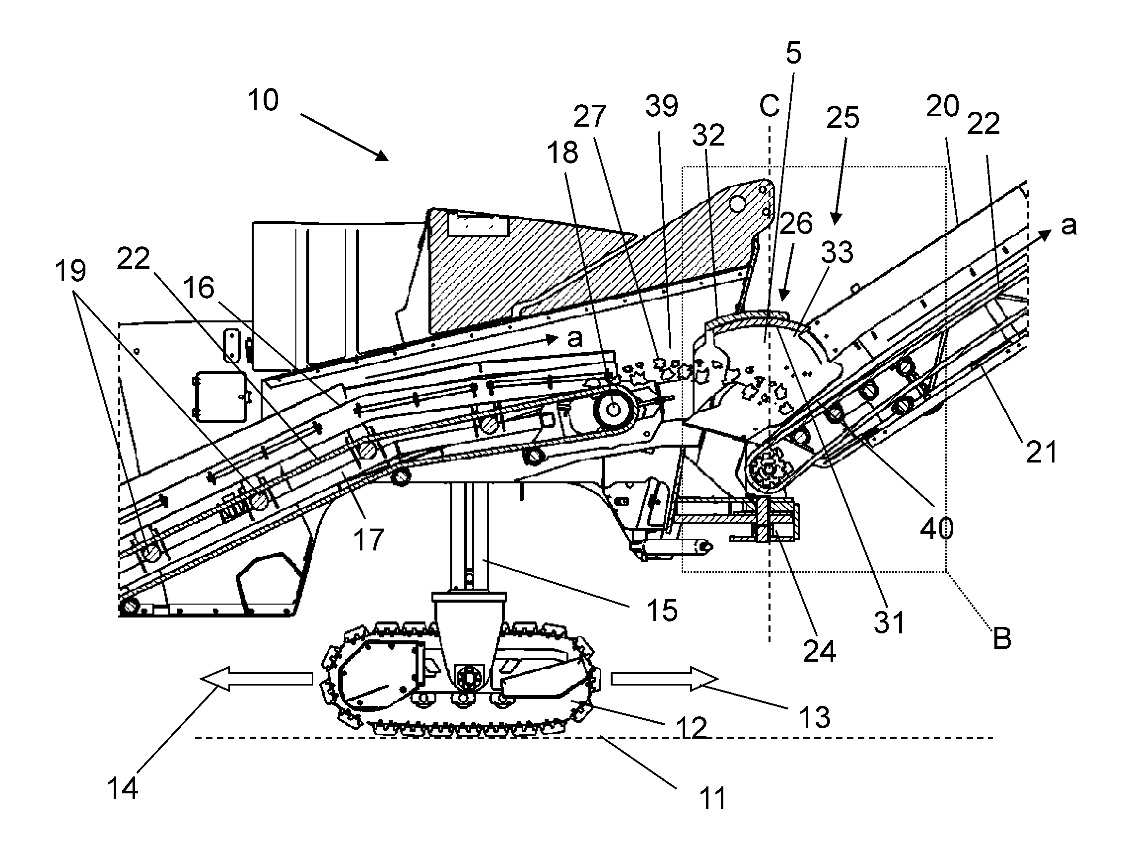
[0024]FIG. 1 relates to a generic ground milling machine 10 as known in the prior art. The ground milling machine 10 according to FIG. 1 specifically concerns a road milling machine of front-loader type with rear rotor in a side view. The ground milling machine 10 travels in the forward direction 13 in working operation (the reverse direction is designated with reference numeral 14), wherein a milling drum, which is not shown in closer detail, is held in a milling drum box 2 and enters the ground 11 to be milled. The milling roller rotates about a horizontal rotational axis extending transversely to the working direction. Further relevant elements of the ground milling machine are a machine frame 3 with an operator platform 4 and crawler tracks 12 which are mounted in a height-adjustable manner by means of ...


PUM


Abstract

The present invention relates to a material transfer apparatus for a road construction machine, and especially a ground milling machine. The material transfer apparatus comprises a material feed area, a material discharge area and a sealing apparatus. According to one aspect of the present invention, the sealing apparatus comprises a first sealing element and a second sealing element, wherein the first sealing element and the second sealing element overlap each other at least in part and form a hollow space, so that ground material to be removed is conveyed in an unobstructed manner from the material feed area to the material discharge area.

Description

CROSS-REFERENCE TO RELATED APPLICATIONS[0001]The present application claims priority under 35 U.S.C. §119 of German Patent Application No. 10 2012 019 016.6, filed Sep. 26, 2012, the disclosure of which is hereby incorporated herein by reference in its entirety.FIELD OF THE INVENTION[0002]The present invention relates to a material transfer apparatus for a ground milling machine, especially a road milling machine, for transferring milled ground material. The material transfer apparatus comprises a material feed area of a transfer conveyor belt, a material discharge area of a loading conveyor belt, and a sealing apparatus with a first sealing element. The present invention further relates to a road construction machine, especially a road milling machine.BACKGROUND OF THE INVENTION[0003]A generic ground milling machine, especially a cold road milling machine, is known from WO 2010 / 045952 A1, for example, wherein reference is hereby made to its disclosure concerning the configuration a...

Claims


Application Information

Patent Timeline
Patent Type & Authority Applications(United States)
IPC IPC(8): B65G37/00E01C23/088E01C23/12
CPCB65G37/00E01C23/088E01C23/127B65G41/002B65G41/008B65G47/58B65G69/181E01C2301/50
Inventor MOTZ, KARL-HERMANNMEURER, MARKUS
Owner BOMAG
Why Eureka
Try Eureka