Device for driving and guiding a rapier of a weaving machine

a technology of weaving machine and rapier rod, which is applied in the direction of weaving, textiles and papermaking, looms, etc., can solve the problems of high heat development, premature wear of rapier rods, and rapid decline of rapier rods, so as to achieve easy and more precise adjustment of clearances, less wear and development of heat

Inactive Publication Date: 2006-01-24
N V MICHEL VAN DE WIELE
View PDF15 Cites 100 Cited by
  • Summary
  • Abstract
  • Description
  • Claims
  • Application Information

AI Technical Summary

Benefits of technology

[0010]The purpose of the present invention is to provide for a drive and guide device for a weaving machine rapier, allowing an easier and more precise adjustment of the clearances between gearwheel and gear-rack, and the working of which, because of an improved adjustment of these clearances, will cause less wear and development of heat.
[0012]With this device, the distance between the drive wheel and the rapier rod can be adjusted in a direction at right angles to the plane of the axis by simply sliding the guide unit. A continuous adjustment of the drive wheel in the direction of the drive shaft makes it possible to mutually modify and adjust the installation of drive wheel and rapier rod, also in the direction of the axis. Both adjustments can be performed very easily and with great precision, so that the said clearances may be adjusted with optimum precision in order to obtain a drive and guide device reducing wear and development of heat to a minimum.
[0017]Preferably, the said guide means comprise a rectilinear air bearing. Such an air bearing is capable of absorbing strong radial forces, so that development of heat is considerably reduced in consequence of which the life of the rapier rods and of the guide bodies is considerably increased. Moreover, the development of heat in the air bearing can be monitored by means of a temperature sensor, so that the weaving machine can be put out of action in case of too sharp a rise in temperature. This may happen, for instance, in consequence of a breakdown of the compressed air supply or of the air inlet holes of the bearing getting clogged. In this way, damage to the rapier rods can be avoided.
[0019]In a particularly preferred embodiment, the device is provided with a guide unit comprising a guide slat, which can be brought into an operative position in which the guide channel is limited on one side and is movable into another position in order to make the guide channel accessible on the said side. In such an embodiment, a rapier rod can be removed from the guide channel very easily.
[0021]In an advantageous embodiment, the said guide means, and more particularly the air bearing, are attached to the guide slat, while the guide slat is adjustable in order to modify the width of the guide channel. Because the guide slat and the guide means are adjustable together, now the adjustment of the width of the guide channel can be carried out very easily and rapidly. It may, for instance, be necessary to adapt the width of the guide channel to a rapier rod having deviating transverse dimensions.
[0025]In a preferred embodiment, the casing for the drive wheel can be fixed in an adjusted position by means of fixing means, in which case fixing and loosening these fixing means may be carried out near a top of said casing. Because the fixing means are well accessible, adjusting the direction of the guide path can be carried out easily and rapidly.

Problems solved by technology

This device has the disadvantage that particularly much heat is developed, and that the rapier rods, especially at relatively high weaving speeds, are subject to premature wear.
If both clearances (the horizontal and the vertical clearances) are not adjusted correctly, this might provoke premature wear of the gear-rack and an exaggerated heating of the rapier envelope, which will cause its rapid decline.
These adjustments of the vertical and horizontal clearances are difficult to perform and cannot be carried out with the required precision and moreover, they are particularly time-consuming and complicated.

Method used


Image

  • Device for driving and guiding a rapier of a weaving machine
  • Device for driving and guiding a rapier of a weaving machine
  • Device for driving and guiding a rapier of a weaving machine

Examples


Embodiment Construction

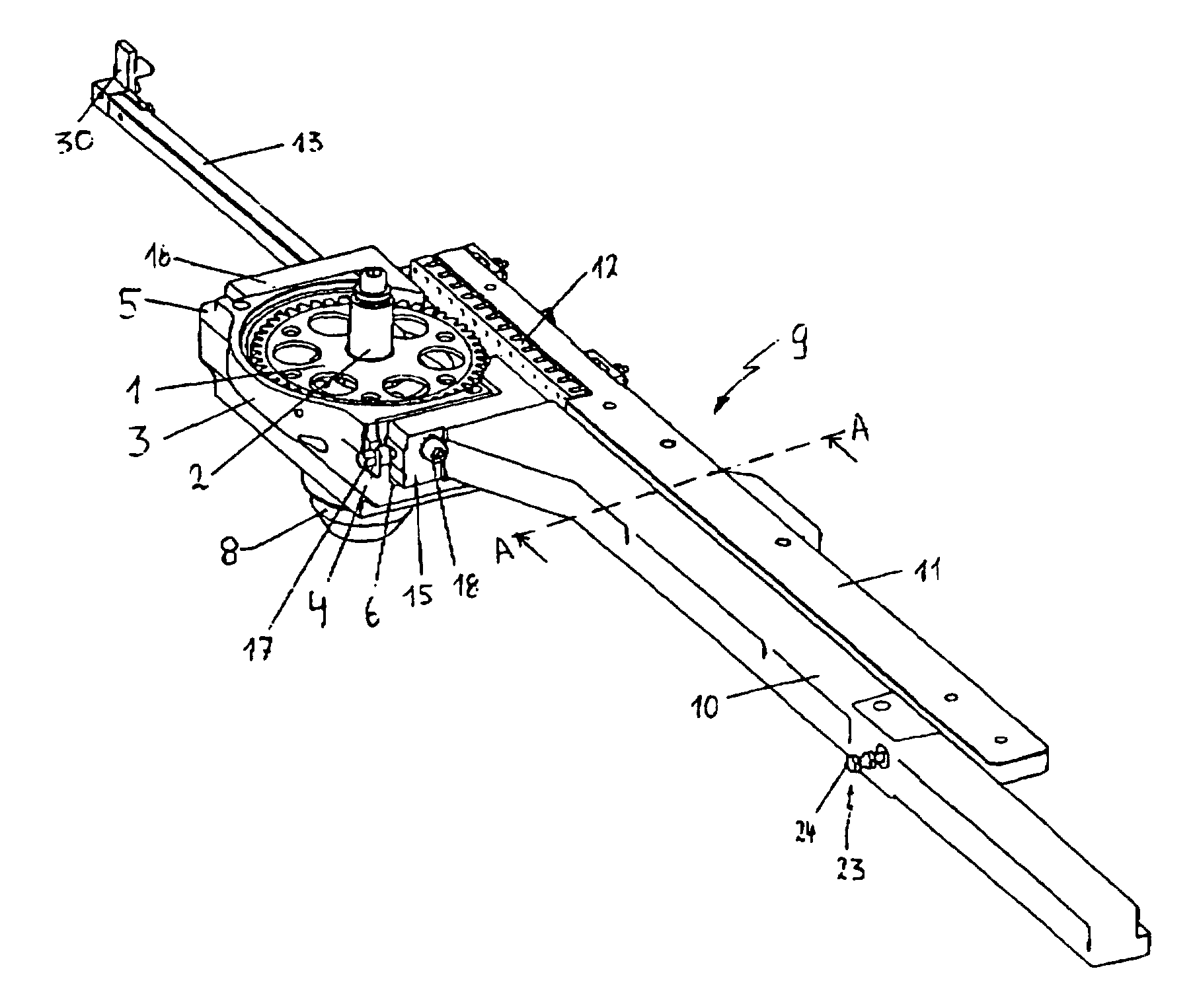
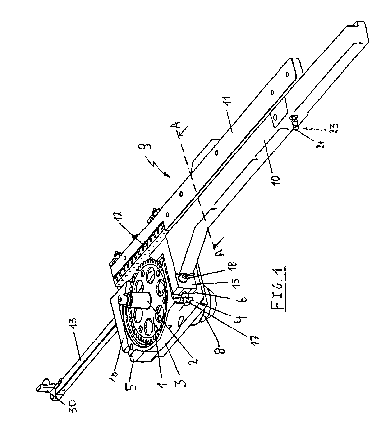
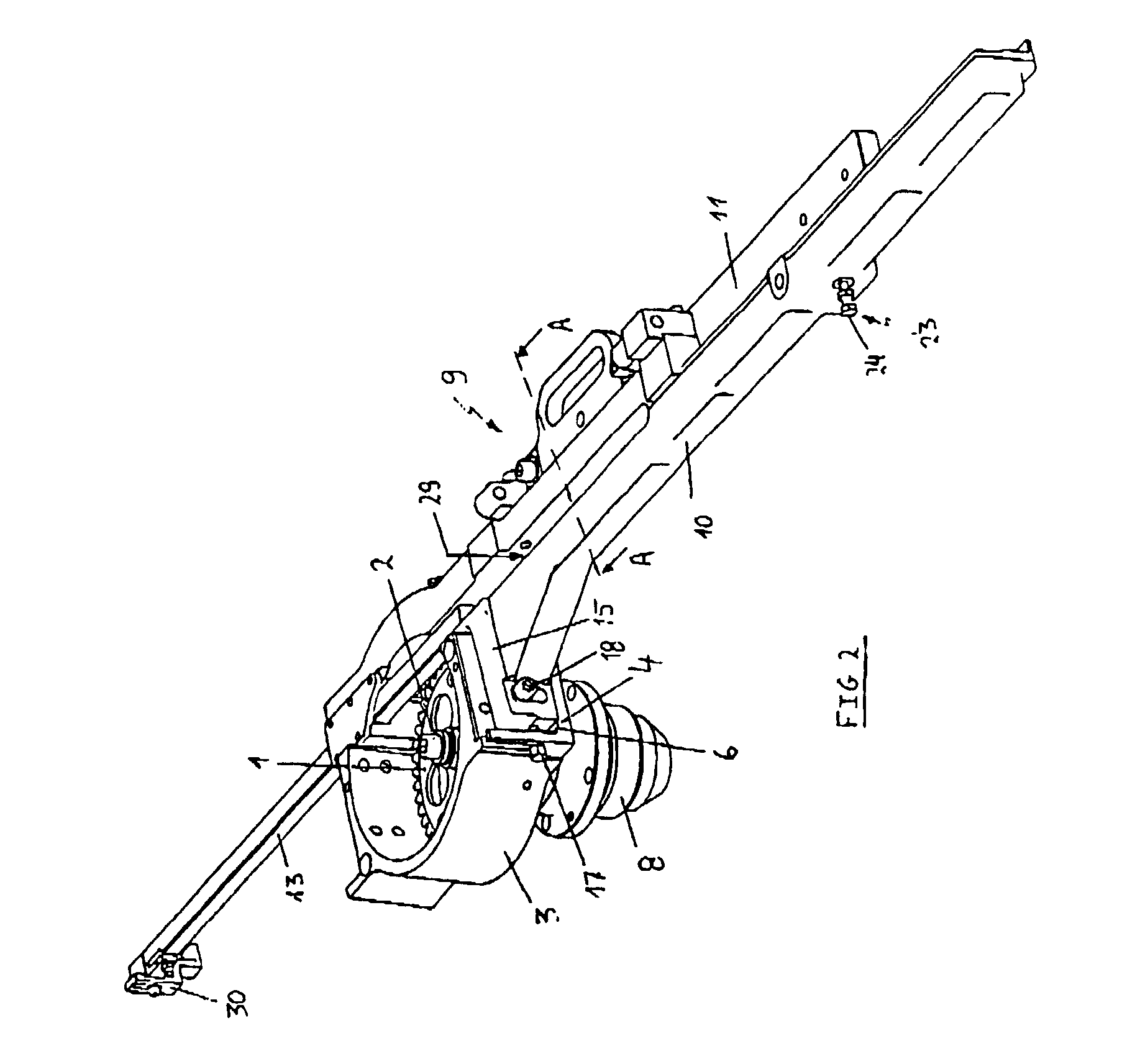
[0042]The drive and guide device represented in the FIGS. 1 and 2 comprises a drive wheel (1) mounted on a drive shaft (2) extending vertically and incorporated in a casing (3), hereafter called “the drive casing (3)”. The drive casing (3) has laterally projecting collars (4),(5) on two opposite flanks, the tops of which constitute a horizontal supporting surface (6), (7) for the legs (15), (16) of the fastening fork to be further described. Under the drive casing (3) a second housing (8) has been provided, (hereafter called “the bearing housing (8)” in which the bearings of the drive shaft have been incorporated.

[0043]A guide unit (9) is attached to the drive casing (3). It consists of an elongated molded supporting part (10) having an L-shaped cross-section (hereafter called “the L-section (10)”, a guide ruler (11) with built-in air bearing (12) hingedly connected to this L-section (10) and an extensible rod (13), forming a whole together. Between the L-section (10) and the guide ...


PUM


Abstract

A device for driving and guiding a rapier of a weaving machine, comprises a rotatable drive wheel (1) provided for driving a rapier rod (14) in a back and forth movement and a guide channel formed by adjustable guide bodies (10), (11) in order to guide the said rapier rod (14) according to a guide path in co-operation with the drive wheel (1). The guide bodies (10), (11) are part of a guide unit (9) which, as a whole, is adjustable in order to modify the distance between the guide path and the rotation shaft (2) of the drive wheel (1), and where the drive wheel (1) is continuously adjustable in the longitudinal direction of its shaft (2). With this device the clearances of the rapier rod with respect to the drive wheel can be performed easily, rapidly and with great precision, so that this device is able to work with a minimum development of heat and wear.

Description

[0001]This application claims the benefit of Belgian Application No. 2001 / 0563 filed Aug. 29, 2001.BACKGROUND OF THE INVENTION[0002]This invention relates to a device for driving and guiding a rapier of a weaving machine, comprising a rotatable drive wheel provided for driving a rapier rod in a back and forth movement, and a guide channel formed by adjustable guide bodies in order to guide the said rapier rod according to a guide path in co-operation with the drive wheel. This invention further relates to a rapier weaving machine provided with at least one such drive and guide device.[0003]A rapier weaving machine is equipped with one or more rapier systems, each rapier system comprising two cooperating rapiers. Each rapier system is provided for inserting a weft yarn into a shed formed between the warp yarns each time in successive inserting cycles. In each inserting cycle, the rapiers situated on either side of the shed are first moved towards one another in this shed, while the o...

Claims


Application Information

Patent Timeline
Patent Type & Authority Patents(United States)
IPC IPC(8): D03D47/04D03D47/27
CPCD03D47/271D03D47/27D03D47/273D03D47/275D03D47/276D03D47/277
Inventor DEBAES, JOHNYMAES, DOMINIQUEHULLEBUSCH, JO
Owner N V MICHEL VAN DE WIELE
Why Eureka
Try Eureka