
Device and method for polarization control for a phased array antenna

a phased array and antenna technology, applied in the field of antennas, can solve the problems of increasing the difficulty of implementation at high microwave frequency, significant impact on array cost and power consumption/disassembly per element, and complex polarization control in phased arrays

Inactive Publication Date: 2008-10-14
L 3 COMM TITAN CORP
View PDF23 Cites 41 Cited by
  • Summary
  • Abstract
  • Description
  • Claims
  • Application Information

AI Technical Summary

Problems solved by technology

This makes the problem of polarization control in phased arrays more complex than the above noted case of polarization control in reflector antennas.
This has a very significant impact on the array cost and power consumption / dissipation per element.
It may also increase the difficulty of implementation at high microwave frequencies where the space for components behind each radiator element is limited.

Method used


Image

  • Device and method for polarization control for a phased array antenna
  • Device and method for polarization control for a phased array antenna
  • Device and method for polarization control for a phased array antenna

Examples


Embodiment Construction

[0040]Referring now to the drawings in figures, some preferred embodiments of the present invention in current preferred modes in accordance with the present invention are shown. However, the drawings depicted should in no fashion be considered as limiting the device and method and any and all changes or other embodiments that would occur to those skilled in the art are considered within the scope of this invention.

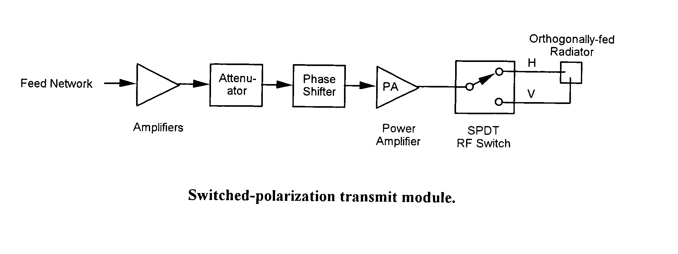
[0041]As noted the disclosed method and apparatus relates to the control of the polarization of phased array antennas as applicable in the fields of satellite communication, terrestrial line-of-sight communication and radar. The method herein disclosed provides a method of controlling the polarization of a phased array antenna in which each radiator element radiates or receives signals in one of two orthogonal, switch-selected polarizations (e.g., horizontal or vertical) by controlling the individual switches of each element to place each element in the desired polarizati...


PUM


Abstract

A method of configuring a phased array antenna having a plurality of radiators, each said radiator elements capable of radiating or receiving signals in one of two orthogonal polarizations determined to achieve a pseudo-random mix of horizontally and vertically polarized radiators. Upon switching of each of the radiator elements to a calculated one of said two polarizations, a desired slant angle for the antenna is achieved.

Description

FIELD OF THE INVENTION[0001]This application claims the benefit of U.S. Provisional Application Ser. No. 60 / 727,051 filed on Oct. 14, 2005, which is incorporated herein by reference. The present invention relates generally to antennas. More particularly, it relates to an apparatus and method for control of the polarization of a phased array antenna which dynamically allocates the individual polarization of radiator elements between individual horizontal and vertical polarization modes, to control the overall polarization of the radiated signal of the antenna.BACKGROUND OF THE INVENTIONGeostationary Communication Satellites[0002]Satellite communications utilizes electromagnetic waves to carry information from the ground to space and back. An electromagnetic wave consists of an electric field and a magnetic field that are perpendicular to each other and to the direction of propagation. Polarization is a term that defines the orientation of the electric field as the wave propagates thr...

Claims


Application Information

Patent Timeline
Patent Type & Authority Patents(United States)
IPC IPC(8): H01Q19/00
CPCH01Q21/061H01Q21/245
Inventor BLANTON, JAMES L.
Owner L 3 COMM TITAN CORP
Learn More