Hall thrustor based on magnetic focusing

A Hall thruster, magnetic focusing technology, applied in thrust reversers, machines/engines, plasma utilization, etc., can solve problems such as performance change, breakdown of channel ceramic walls, thruster failure, etc.

Inactive Publication Date: 2012-06-13
HARBIN INST OF TECH
View PDF1 Cites 23 Cited by
  • Summary
  • Abstract
  • Description
  • Claims
  • Application Information

AI Technical Summary

Problems solved by technology

[0004] In order to solve the problem that the existing Hall thruster is sputtered and bombarded by high-energy ions on the wall surface material, the cera

Method used


Image

  • Hall thrustor based on magnetic focusing
  • Hall thrustor based on magnetic focusing
  • Hall thrustor based on magnetic focusing

Examples


specific Embodiment approach 1

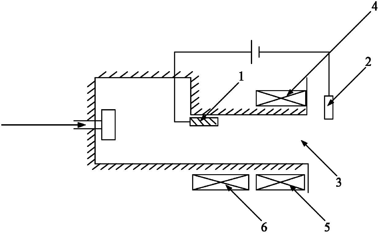
[0010] Specific implementation mode one: combine Figure 1 to Figure 5 To illustrate this embodiment, the Hall thruster based on magnetic focusing in this embodiment includes an anode 1, a cathode 2, a discharge channel 3, an outer coil 4 and an inner coil 5; the anode 1 is arranged in the middle of the discharge channel 3, and the The cathode 2 is arranged at the outlet of the discharge channel 3; the anode 1 is connected to the positive pole of the discharge power supply, the cathode 2 is connected to the negative pole of the discharge power supply, and the outer coil 4 and the inner coil 5 are symmetrically arranged on both sides of the outlet of the discharge channel 3, so After the external coil 4 and the internal coil 5 are energized and excited, an excitation circuit is formed to form a magnetic field in the discharge channel; and the magnetic field configuration is generated in the internal channel of the discharge channel 3 by changing the excitation current intensity ...

specific Embodiment approach 2

[0014] Specific implementation mode two: combination figure 1 Describe this embodiment, the difference between this embodiment and the specific embodiment is that the Hall thruster also includes an additional coil 6, and the additional coil 6 is arranged side by side on the side where the inner coil 5 is away from the outlet of the discharge channel 3, and the additional coil 6 is used for It is used to fine-tune the configuration of the magnetic field generated by the outer coil 4 and the inner coil 5 in the inner channel of the discharge channel 3 . Other compositions and connection methods are the same as those in Embodiment 1.

specific Embodiment approach 3

[0015] Embodiment 3: This embodiment differs from Embodiment 2 in that the distance between the inner coil 5 and the additional coil 6 is 2 mm. Other compositions and connection methods are the same as those in the second embodiment.

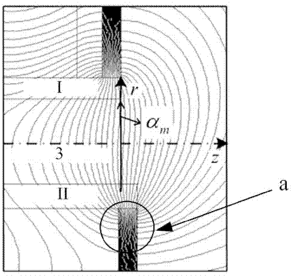
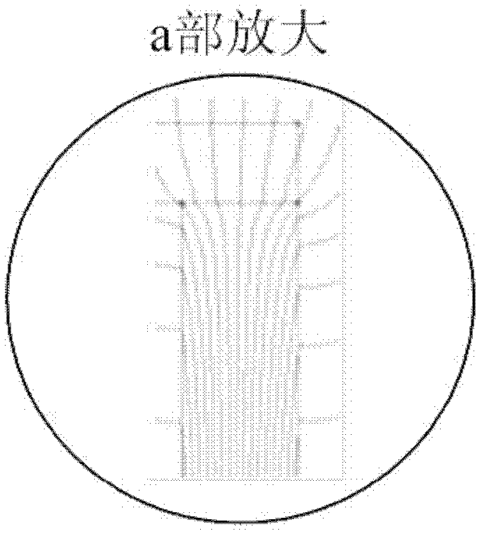
[0016] Principle: By adjusting the excitation current intensity of the inner coil 4, the outer coil 5, and the additional coil 6, a focused magnetic field configuration is formed in the discharge channel of the Hall thruster, and a potential distribution that can effectively control the divergence of the ion current is obtained. Compared with the non-focused magnetic field, the potential distribution in the discharge channel under the condition of the focused magnetic field can effectively control the divergence of the ion beam. The PIC numerical simulation method is used to count the bombardment parameters of the ion on the wall under the focused magnetic field and the divergent magnetic field. For example, the statistical results show that the...


PUM


Abstract

A Hall thrustor based on magnetic focusing relates to a Hall thrustor and aims to resolve the problem that in an existing Hall thrustor, as high-energy ions sputter and force out wall surface materials, a ceramic wall surface of a channel is punctured, so that performances of the existing Hall thrustor are greatly changed, and finally the thrustor is failure. An anode is arranged in the middle of a discharge channel, and a cathode is arranged at an outlet of the discharge channel; an outer coil and an inner coil are symmetrically arranged on two sides of the outlet of the discharge channel, and respectively generate axial magnetic induction strength and radial magnetic induction strength; a slant angle of each magnetic line of force of magnetic field configurations generated by the outer coil and the inner coil is am, and two magnetic field configurations are generated by means of changing exciting current intensity of the outer coil 4 and the inner coil 5; if the magnetic lines of force are coincident to a radial direction, the am equals to 0 degrees; and if the magnetic lines of force are inclined to the direction of the anode 1, the am is smaller than 0 degree. A method of reducing erosion of a wall surface of the channel and prolonging the service life of the thrustor is realized by means of affecting sputtering parameters including ion flux, energy, incident angles and the like of a forced-out wall surface.

Description

technical field [0001] The invention relates to the field of electric propulsion in aerospace propulsion, in particular to a Hall thruster. Background technique [0002] Hall thruster is a kind of electric propulsion device, which is widely used in high-orbit satellite attitude maintenance, orbit transfer and other fields. The Hall thruster ionizes the inert gas working medium by heating the electrons through the electric field, and the ionized ions are accelerated and ejected under the action of the accelerating electric field to generate thrust. [0003] The study found that the most important reason limiting the service life of the Hall thruster is: the sputtering erosion caused by the ion beam divergence in the accelerating channel to the bombardment of the inner and outer walls. In the discharge channel, the movement of working fluid atoms before ionization belongs to diffusion movement, and there is a radial movement component. The ions generated by ionization inherit...

Claims


Application Information

Patent Timeline
IPC IPC(8): F03H1/00H05H1/00
Inventor 丁永杰于达仁颜世林宁中喜
Owner HARBIN INST OF TECH
Why Eureka
Try Eureka