Autostereoscopic image output device

a technology of autostereoscopic image and output device, which is applied in the field of autostereoscopic image output device, can solve the problems of more or less vertical lens arrangement, unfavorable view separation and pixel structure, and achieve good view-distribution and image pixel structure, and sufficient slant

Active Publication Date: 2011-01-06
KONINKLIJKE PHILIPS ELECTRONICS NV
View PDF28 Cites 25 Cited by
  • Summary
  • Abstract
  • Description
  • Claims
  • Application Information

AI Technical Summary

Benefits of technology

[0015]The invention provides a specific range of slant angles which enables a 3D image device to be used in both the landscape and the portrait mode, while maintaining a...

Problems solved by technology

Because the sub-pixels now extend into the horizontal direction instead of the vertical direction, a more o...

Method used


Image

  • Autostereoscopic image output device
  • Autostereoscopic image output device
  • Autostereoscopic image output device

Examples


Embodiment Construction

[0033]The invention provides a lens array with a specific range of slant angles, including a preferred value of slant (defined as tan φ) of tan φ=2 / 3. This enables a 3D display to be used in both the landscape and the portrait mode.

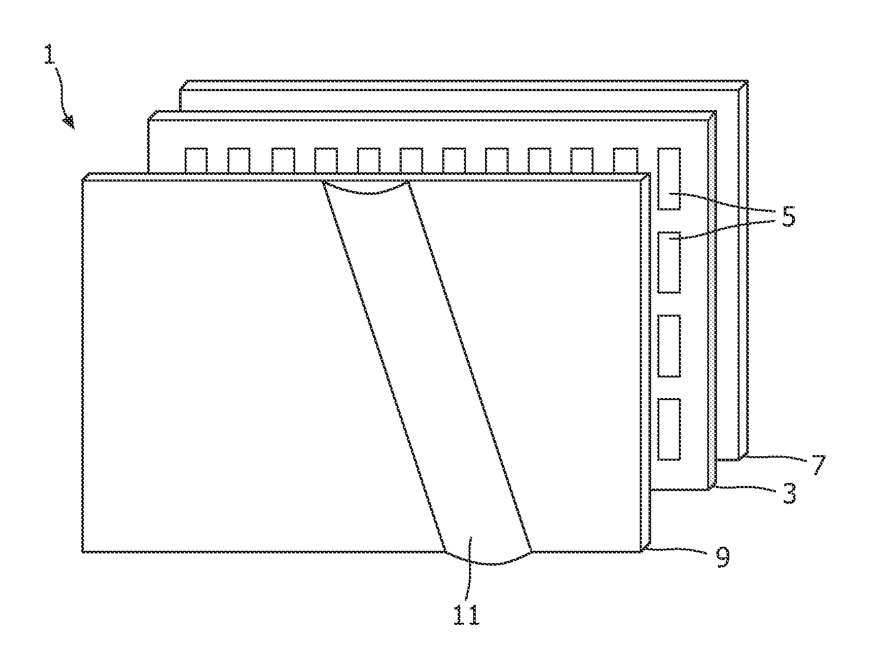
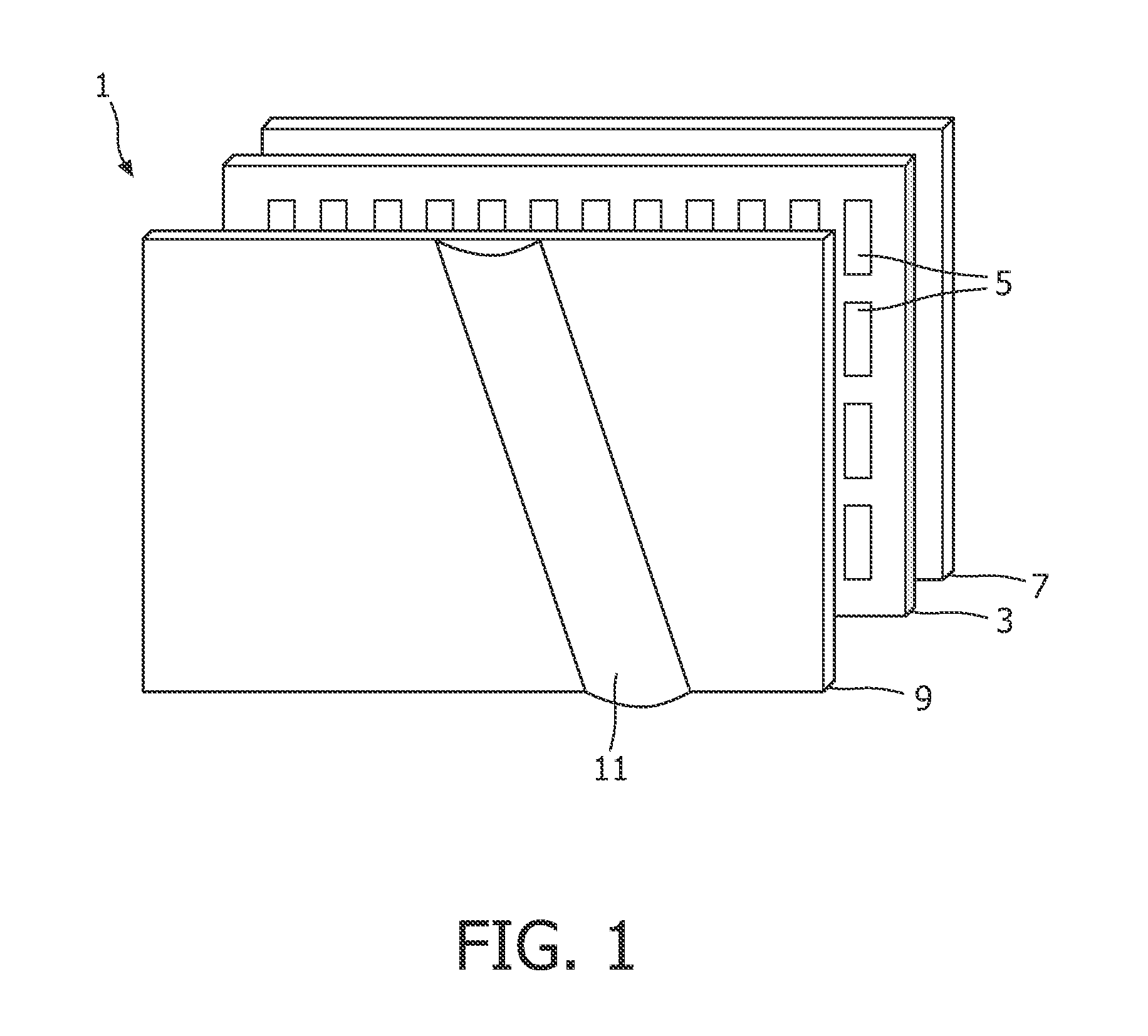
[0034]FIG. 1 is a schematic perspective view of a known direct view autostereoscopic display device 1. The known device 1 comprises a liquid crystal display panel 3 of the active matrix type that acts as a spatial light modulator to produce the display. Other types of display producing panels may be used such as cathode ray tube or light emitting diode panels.

[0035]The display panel 3 has an orthogonal array of display pixels 5 arranged in rows and columns. For the sake of clarity, only a small number of display pixels 5 are shown in the Fig. In practice, the display panel 3 might comprise about one thousand rows and several thousand columns of display pixels 5.

[0036]The structure of the liquid crystal display panel 3 is entirely conventional. In particul...


PUM


Abstract

An autostereoscopic image output device comprises an image panel having an array of image pixels (5) defining an image, the image pixels being arranged in rows and columns. An array of parallel lenticular elements (11) is positioned over the image panel, the lenticular elements having optical focal axes that are slanted at an angle (φ) to the image pixel columns. The image output device is operable in first and second modes, with the image panel and lenticular element array rotated by 90 degrees between the modes, thereby providing a landscape mode of operation and a portrait mode of operation, the slant angle φ in the landscape mode satisfies: 1≧tan φ≧1/2. This enables a 3D image device to be used in both the landscape and the portrait mode, while maintaining a good view-distribution and image pixel structure.

Description

FIELD OF THE INVENTION[0001]This invention relates to an autostereoscopic image output device comprising an image panel and a plurality of lenticular elements arranged over the image panel and through which the image is viewed.BACKGROUND OF THE INVENTION[0002]A known autostereoscopic display device is described in the paper entitled “Multiview 3D-LCD” by C. van Berkel et al. in SPIE Proceedings, Vol. 2653, 1996, pages 32-39. This known device comprises a two dimensional liquid crystal display panel having a row and column array of display pixels acting as a spatial light modulator to produce the display. An array of elongate lenticular elements extending parallel to one another overlies the display pixel array, and the display pixels are observed through these lenticular elements.[0003]The lenticular elements are provided as a sheet of elements, each of which comprises an elongate semi-cylindrical lens element. The lenticular elements extend in the column direction of the display pa...

Claims


Application Information

Patent Timeline
IPC IPC(8): H04N13/04
CPCH04N13/0415H04N13/0404H04N13/305H04N13/317
Inventor DE ZWART, SIEBE TJERKHIDDINK, MARTIN GERARD HENDRIKNIESSEN, EDUARDOUWERKERK, MARTIN
Owner KONINKLIJKE PHILIPS ELECTRONICS NV
Why Eureka
Try Eureka