Resolution For Autostereoscopic Video Displays

a video display and autostereoscopic technology, applied in the field of autostereoscopic video displays, can solve the problems that conventional video display devices are incapable of providing enough views in a sufficiently small space to satisfy the demands of modern autostereoscopic, and achieve the effect of reducing the curvature of the individual lenticles of the lenticular array field and reducing the focus errors

Active Publication Date: 2017-07-06
SOLIDDD
View PDF7 Cites 11 Cited by
  • Summary
  • Abstract
  • Description
  • Claims
  • Application Information

AI Technical Summary

Benefits of technology

[0011]In addition, focus errors due to curvature of field of the individual lenticles of a lenticular array are reduced by configuring the lenticles to focus at an acceptable distance behind the target of focus, e.g., the pixels of the autostereoscopic display. The result is that, due to curvature of field, the lenticles will focus particularly well at moderate angles of viewing perspective and will still produce acceptable focus errors and even wider angles of viewing perspective.

Problems solved by technology

Thus, conventional video display devices are incapable of providing enough views in a sufficiently small space to satisfy the demands of modern autostereoscopic images.

Method used


Image

  • Resolution For Autostereoscopic Video Displays
  • Resolution For Autostereoscopic Video Displays
  • Resolution For Autostereoscopic Video Displays

Examples


Embodiment Construction

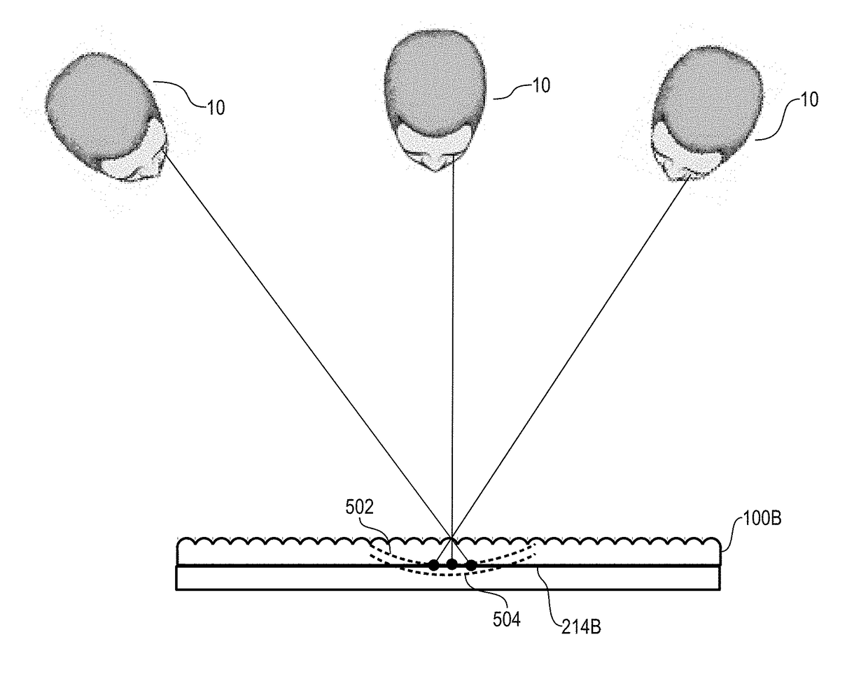
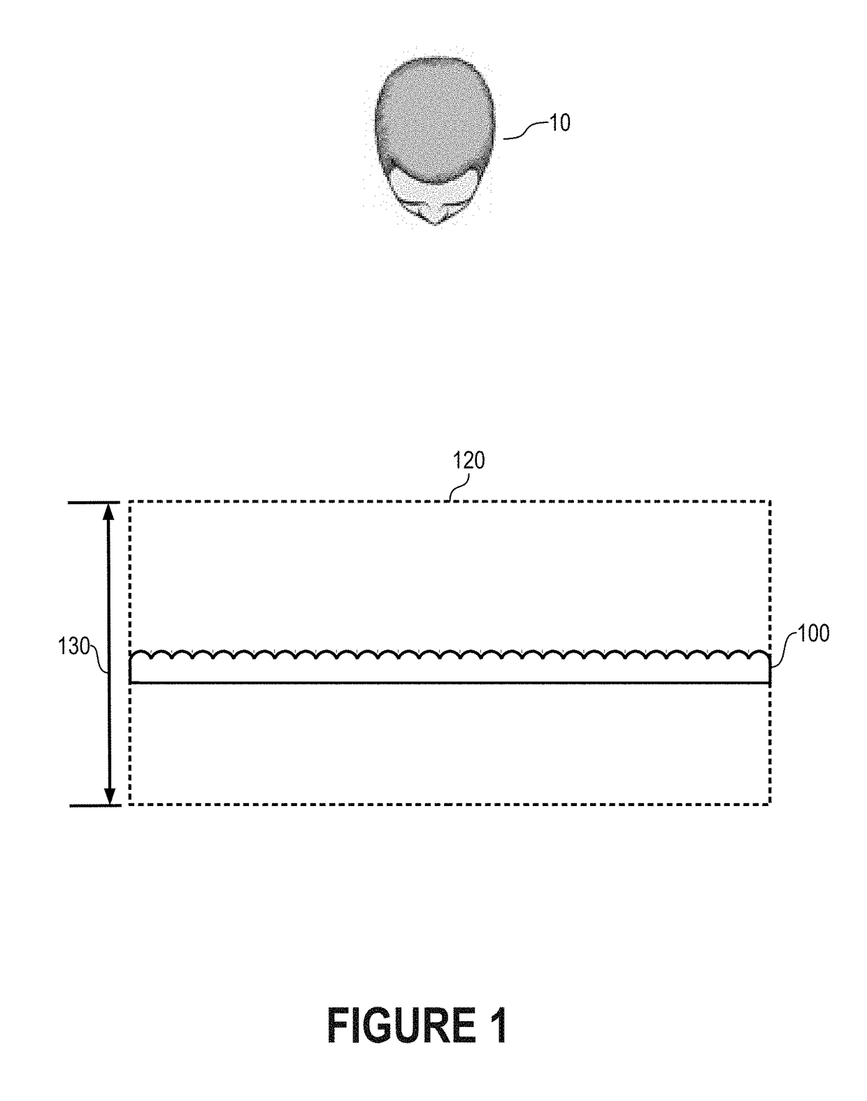
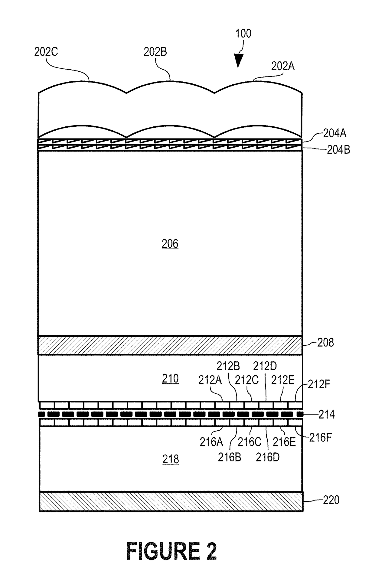
[0022]In accordance with the present invention, a single pixel of a video display can display respective individual pixels of multiple views. In particular, a stereoscopic display 100 (FIGS. 1 and 2) includes view multiplexers 204A-B (FIG. 2) that bend light from each of a number of pixels, such as pixels 216A-F, such that each pixel appears to be at a slightly different location and represents a pixel of a different view for each of a number of multiple time intervals. For example, view multiplexers 204A-B can cause pixel 216A to be at any of locations 216A1 (FIG. 11), 216A2, 216A3, and 216A4. In this manner, each of pixels 216A-F is time-multiplexed to represent pixels of respective multiple views of an autostereoscopic display.

[0023]In a manner described more completely below, view multiplexers 204A-B combine to provide 4-to-1 multiplexing in this illustrative embodiment. View multiplexers 204A-B bend light from pixels 216A-F at predetermined, fractional view angles at predetermi...


PUM


Abstract

A single pixel of a video display can display respective individual pixels of multiple views. In other words, a video display can include more views for an autostereoscopic image than the physical pixels of the video display would ordinarily support. The physical pixel is time-multiplexed in that the physical pixel displays a pixel of one view for a given time interval and a view multiplexer deflects the light from the physical pixel by a predetermined angle to make the pixel appear in a location corresponding to the pixel of the view. In another time interval, the physical pixel displays a pixel of a different view and the view multiplexer deflects light from the physical pixel by a different predetermined angle to make the pixel appear in a location corresponding to the pixel of the different view.

Description

FIELD OF THE INVENTION[0001]The present invention relates generally to autostereoscopic displays, and, more particularly, to a video autostereoscopic display with significantly improved resolution.BACKGROUND OF THE INVENTION[0002]Conventional autostereoscopic displays use arrays of lenses or parallax barriers or other view selectors to make a number of pixels of the display visible to one eye of a viewing person and to make a number of other pixels of the display visible to the other eye of the viewing person. By isolating the pixels of the display visible to each eye, the two components of a stereoscopic image can be presented on the display.[0003]Since an ordinary viewer's eyes are side-by-side and aligned horizontally, the array of lenses makes pixels visible according to horizontal orientation. As a result, corresponding pixels for the left and right eyes are located in the same scanline and displaced from one another horizontally.[0004]Each eye of the viewer therefore sees an i...

Claims


Application Information

Patent Timeline
Patent Type & Authority Applications(United States)
IPC IPC(8): H04N5/265H04N13/04G02B30/27H04N13/305
CPCH04N5/265H04N13/0406H04N13/0402H04N13/305H04N13/229H04N13/354H04N13/302G02B30/24G02B30/25G02B30/27
Inventor MULLER, RICHARD A.WEINSTOCK, NEAL
Owner SOLIDDD
Why Eureka
Try Eureka