Display device

a display panel and display technology, applied in the field of display devices, can solve the problems of low transmittance of the display panel, inability to correct the imbalance of display colors, and inability to reduce the brightness

Active Publication Date: 2014-07-03
TRIVALE TECH LLC
View PDF1 Cites 14 Cited by
  • Summary
  • Abstract
  • Description
  • Claims
  • Application Information

AI Technical Summary

Problems solved by technology

This results in a lower transmittance of the display panel than that of an image display device that displays only a single image, which decreases brightness.
However, the imbalance in display colors cannot be corrected after manufacturing of the panel and, for example, color adjustment of correcting the imbalance in display colors due to variations in a manufacturing process cannot be performed.

Method used


Image

  • Display device
  • Display device
  • Display device

Examples


first preferred embodiment

[0020](Principles of Invention: Outline of Structure of Liquid Crystal Parallax Barrier System Auto-Stereoscopic Display)

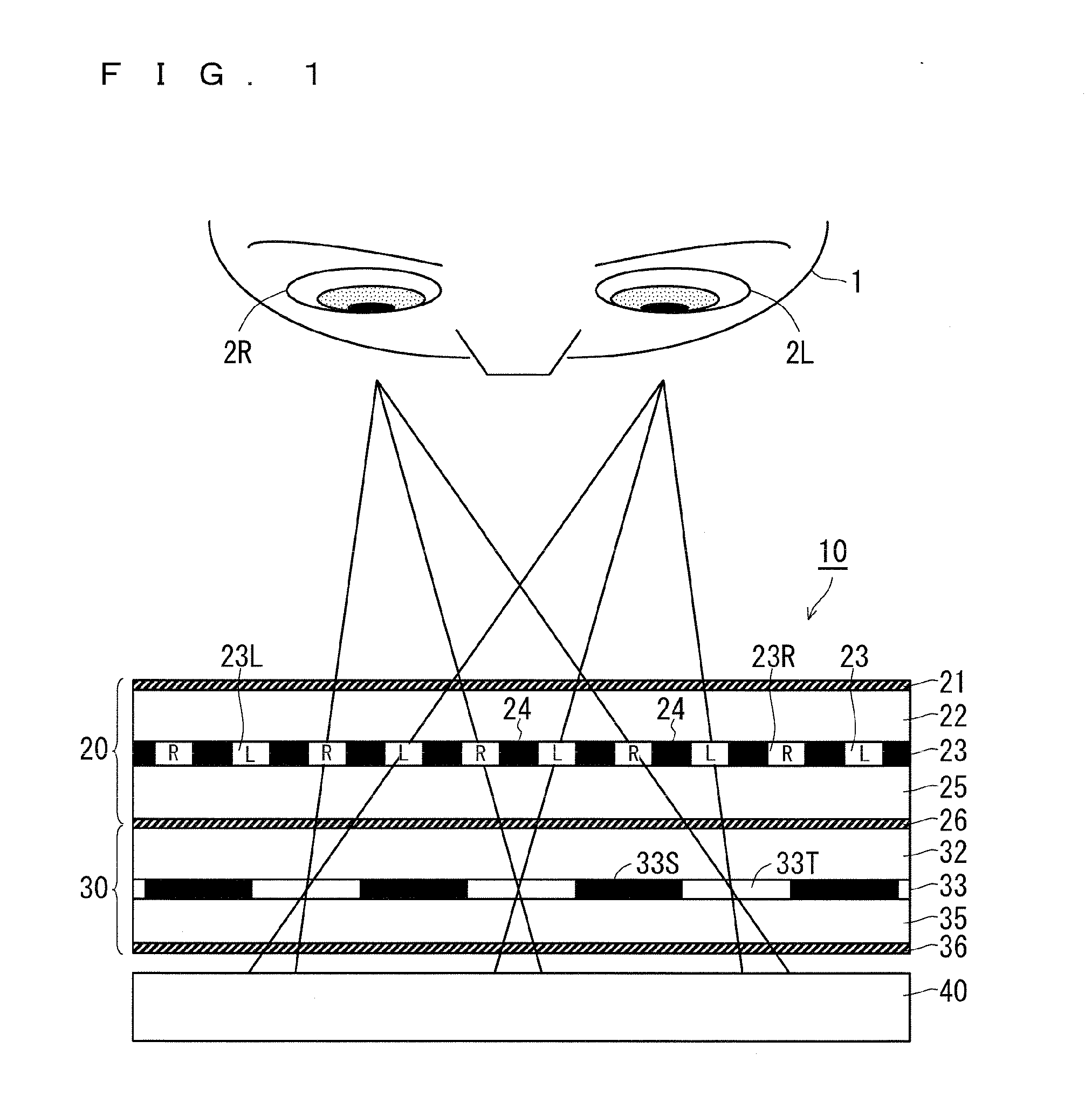
[0021]FIG. 1 is a cross-sectional view showing a configuration of a display device (auto-stereoscopic display device of the liquid crystal parallax barrier system) according to a first preferred embodiment of the present invention. An auto-stereoscopic image display device 10 is capable of simultaneously displaying two images (3-dimensional image) composed of a right image (parallax image for right eye (image for first observation direction; type 1 image)) and a left image (parallax image for left eye that slightly differs from the parallax image for right eye (image for second observation direction; type 2 image)).

[0022]The auto-stereoscopic image display device 10 allows visual recognition of a stereoscopic image with naked eyes without the use of special glasses or allows display of images different from one observation direction to another. A case in which the...

second preferred embodiment

[0068](Liquid Crystal Display Device Capable of Adjusting Coloration of Color Display Even after Manufacturing of Panel)

[0069]FIGS. 5A and 5B are cross-sectional views showing a configuration of a display panel 50 according to a second preferred embodiment of the present invention. Similarly to the display panel 20 according to the first preferred embodiment, the display panel 50 according to the second preferred embodiment is a display panel that performs image display with multiple pixels arranged in matrix, where an in-plane switching mode is adopted as a liquid crystal mode.

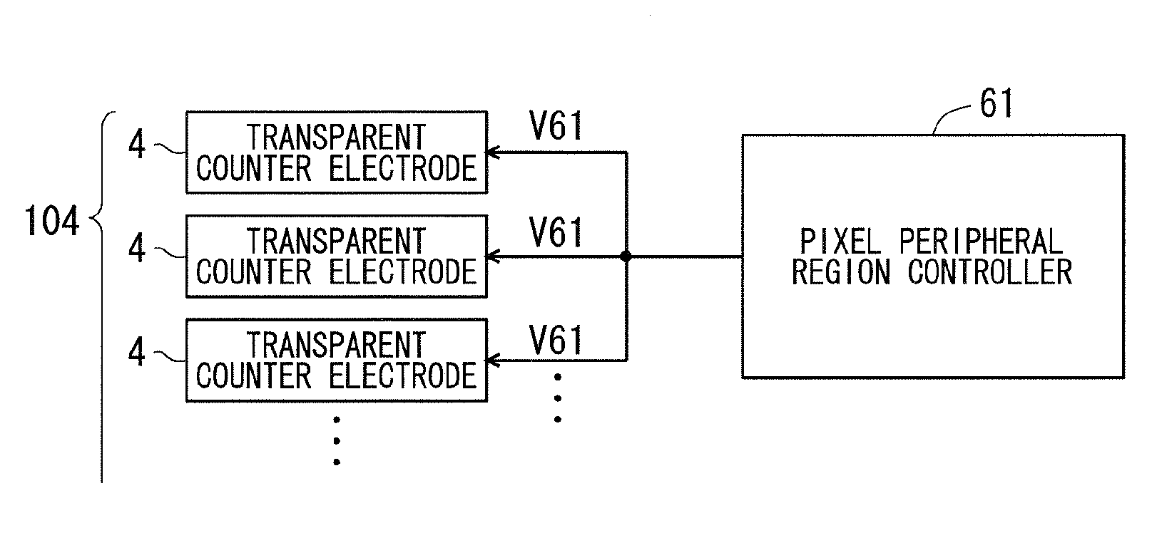
[0070]As the structure characteristic of this preferred embodiment, transparent counter electrodes 44 are arranged in regions corresponding to pixel peripheral regions of a liquid crystal layer 53, on a transparent substrate 52 side of the respective pixels of a liquid crystal panel that performs color display with a color material film 57C of a color filter layer 57 for red, green, and blue (R, G, and B) bei...


PUM

PropertyMeasurementUnit
voltage VBaaaaaaaaaa
voltage VAaaaaaaaaaa

Abstract

A one-pixel structure of a display panel included in an auto-stereoscopic image display device adopts an in-plane switching mode. Transparent counter electrodes that are not provided in a liquid crystal panel of a normal in-plane switching mode are formed correspondingly to pixel peripheral regions on a second transparent substrate side and, in 3-dimensional image display, a vertical electric field is forcibly generated between the transparent counter electrodes and the comb-shaped electrodes, which causes the liquid crystal molecules to rise to show black display in the pixel peripheral regions. In 2-dimensional image display, meanwhile, the transparent counter electrodes are set to be floating, and the display panel is caused to have a structure substantially equivalent to a structure in which the transparent counter electrodes are not provided, to thereby make the display in pixel peripheral regions identical to the display (brightness) in a pixel main region.

Description

BACKGROUND OF THE INVENTION[0001]1. Field of the Invention[0002]The present invention relates to display devices such as a liquid crystal display device including a liquid crystal display panel, and more particularly, to the brightness adjustment technology in image display.[0003]2. Description of the Background Art[0004]Nowadays, an auto-stereoscopic image display device capable of stereoscopic viewing without special glasses is proposed. For example, Japanese Patent No. 2857429 discloses a 3-dimensional image display device including a barrier generating unit and an image display unit. The barrier generating unit generates parallax barrier stripes through electronic control by a transmissive display element. The image display unit includes a display screen disposed behind a position at which parallax barrier stripes are generated with a predetermined distance therefrom and, in display of a 3-dimensional image, is capable of outputting and displaying on the display screen a multidi...

Claims


Application Information

Patent Timeline
Patent Type & Authority Applications(United States)
IPC IPC(8): G09G3/36G09G5/10
CPCG09G5/10G09G3/3648G09G2300/0426G09G2310/0232G09G3/003G09G2300/0434H04N13/31G09G3/3655G09G3/3413G09G3/3426G09G3/3607G09G3/3696G09G2320/0233G09G2320/0626G09G2320/0666G09G2320/062G09G2320/10
Inventor FUJINO, TOSHIAKINIWANO, YASUNORIKIRA, SYUICHINAGANO, SHINGOYUUKI, AKIMASA
Owner TRIVALE TECH LLC
Why Eureka
Try Eureka