Method for auto-stereoscopic image display with a wavelength filter array

a filter array and auto-stereoscopic technology, applied in the direction of optical radiation measurement, instruments, spectrometry/spectrophotometry/monochromators, etc., can solve the problems of affecting the quality of three-dimensional visualization, affecting the resolution of perspective images, and limited maximum number of views that can be displayed

a filter array and auto-stereoscopic technology, applied in the direction of optical radiation measurement, instruments, spectrometry/spectrophotometry/monochromators, etc., can solve the problems of affecting the quality of three-dimensional visualization, affecting the resolution of perspective images, and limited maximum number of views that can be displayed

US20040245440A1Inactive Publication Date: 2004-12-09PHOENIX 3D

Image

  • Method for auto-stereoscopic image display with a wavelength filter array
  • Method for auto-stereoscopic image display with a wavelength filter array
  • Method for auto-stereoscopic image display with a wavelength filter array

Examples


Embodiment Construction

[0006] Proceeding from the prior art as described, it is the objective of the invention to improve the quality of image rendition in a method of three-dimensional visualization.

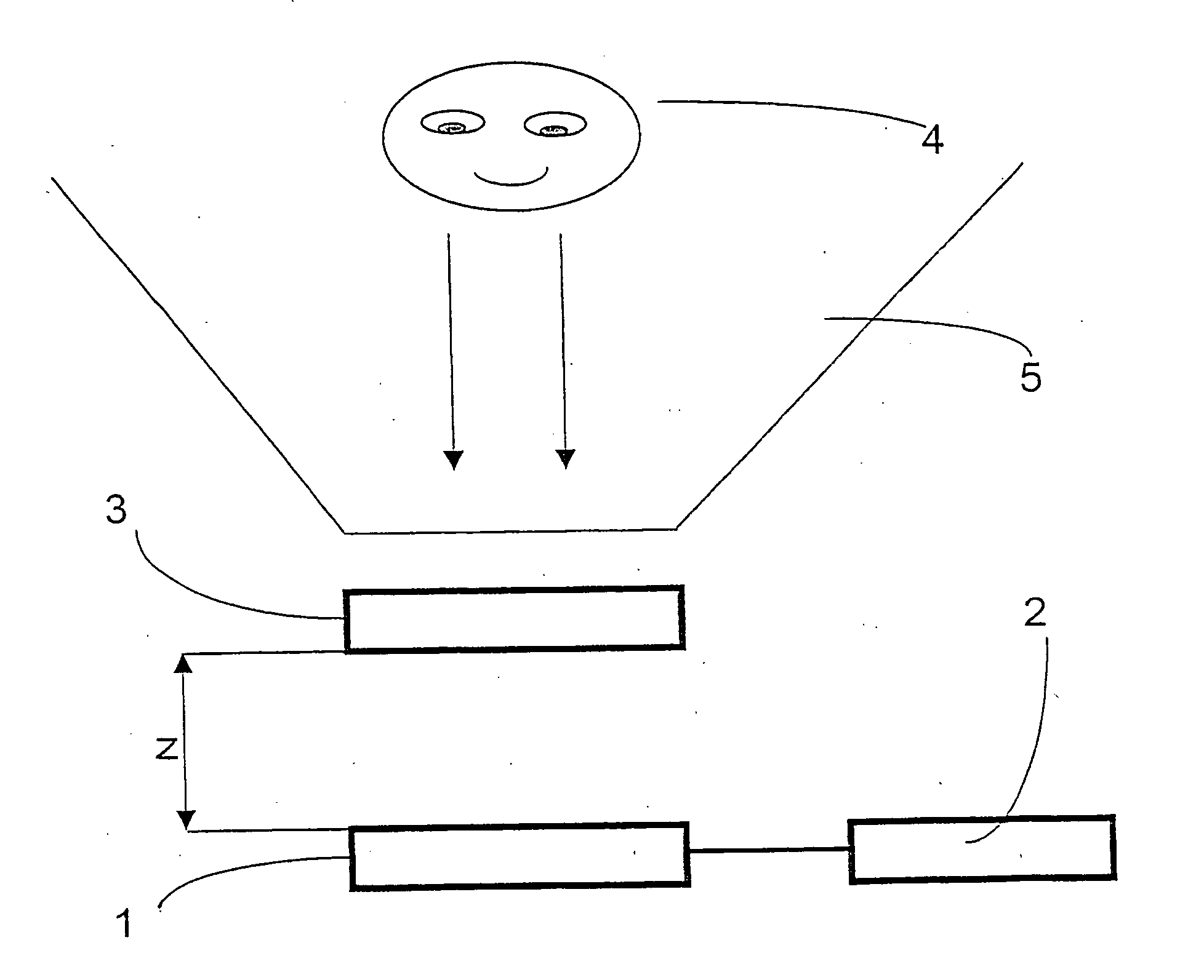
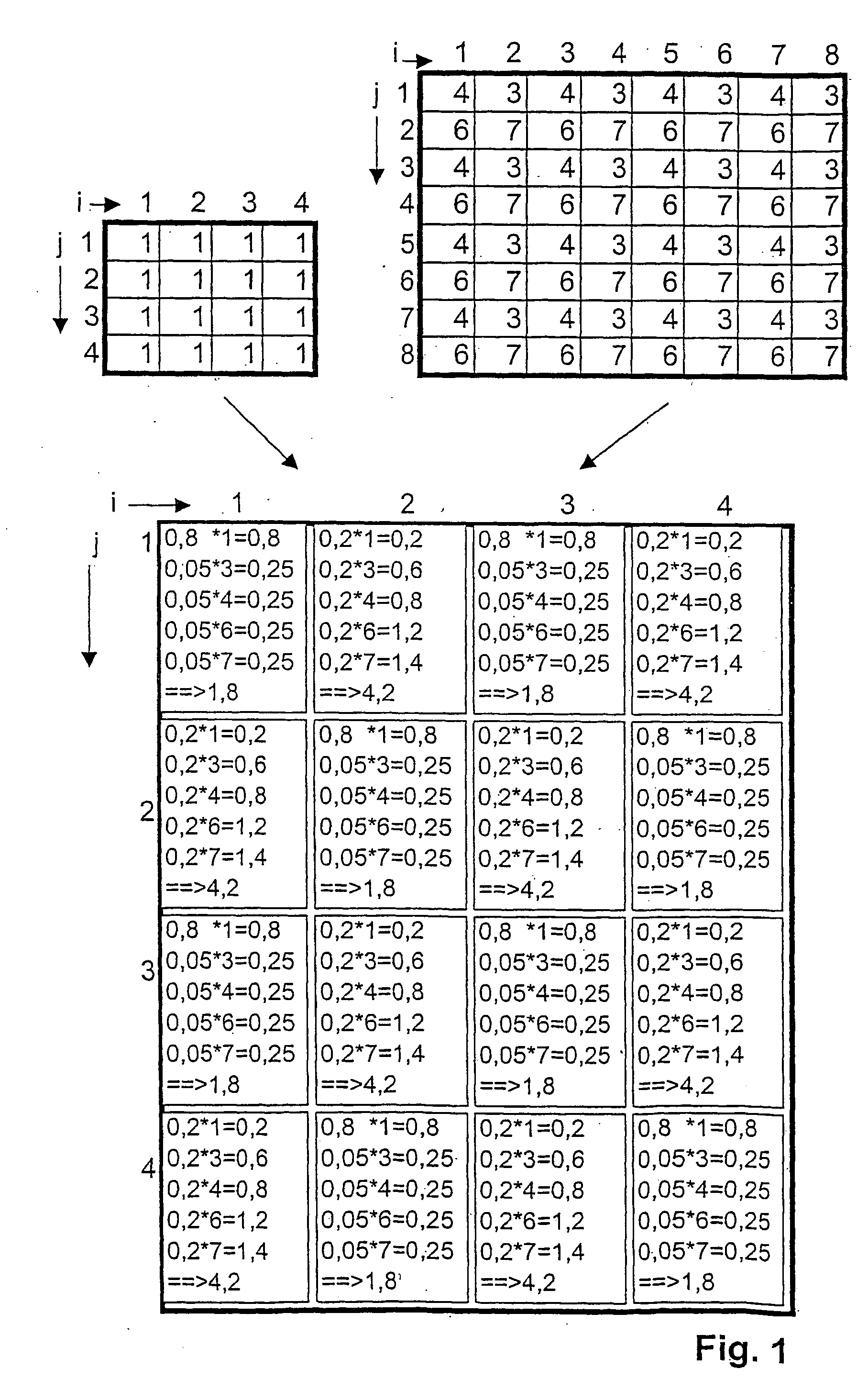
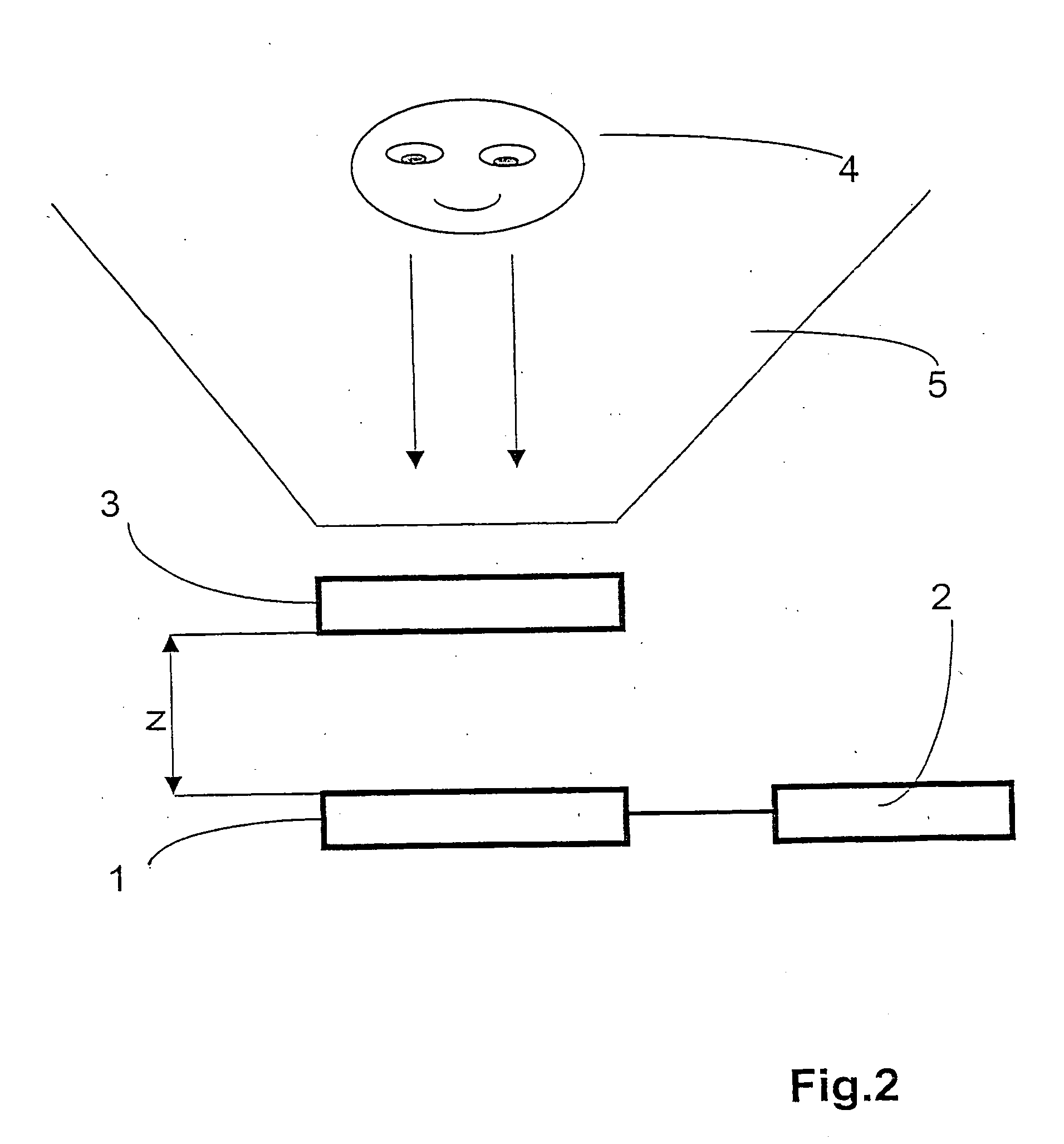
[0007] According to the invention, the objective, in a method of the type described above, is achieved by allocating bits of partial information from at least two different views at a time to at least one image rendering element, this allocation being effected in such a way that the wavelength of the partial information is always equal to the wavelength, or lies in the wavelength range, of the light emitted by the allocated image rendering element.

[0008] If bits of partial information from different views are simultaneously rendered by at least one image rendering element, more views can be used with an image display device of a particular resolution. A greater number of views corresponds to a denser staggering in spatial depth or in perspective, so that the three-dimensional impression is improved. Moreover,...


PUM


Abstract

The invention relates to a method of spatial visualization of a scene or an object, in which several views of the scene or object are decomposed into bits of partial information, which are made optically visible by image rendering elements, and in which neighbored image rendering elements emit light of different wavelengths or wavelength ranges, and in which propagation directions for the light are given by means of wavelength filters in such a way that an observer will see predominantly bits of partial information of a first selection of views with one eye and predominantly bits of partial information of a second selection with the other eye. The invention is intended to improve the quality of spatial visualization. In such a method, at least one image rendering element is simultaneously allocated bits of partial information from at least two different views, the allocation being made in such a way that the wavelength of the partial information is always equal to the wavelength, or lies in the wavelength range, of the light emitted by the allocated image rendering element.

Description

[0001] The invention relates to a method of spatial visualization of a scene or an object on the basis of several views A.sub.c of the scene or object, in which the views A.sub.c on matrices R.sub.c with columns k and rows l are decomposed into many bits of partial information a.sub.ckl characterized by their wavelengths, with c=1, . . . , n and n being the total number of views, and in which the bits of partial information a.sub.ckl are optically presented on image rendering elements .alpha..sub.ij arranged in a matrix of columns i and rows j, and in which neighbored image rendering elements .alpha..sub.ij emit light of different wavelengths or wavelength ranges, and in which propagation directions for the emitted light are given by one or several arrays of many individual wavelength filters arranged in columns and rows, which are transparent for different wavelengths or wavelength ranges and arranged (in viewing direction) in front of or behind the matrix of image rendering elemen...

Claims


Application Information

Patent Timeline
09 Dec 2004
Publication
US20040245440A1
IPC
G02B30/26; G06T19/00; H04N13/00; H04N13/04
CPC
G02B27/225; H04N13/0203; H04N13/0404; H04N13/0409; H04N13/0415; H04N13/0422; H04N13/305; H04N13/324
Inventors
KLIPPSTEIN, MARKUS; RELKE, INGO