Landmine avoidance and protection device

a protection device and landmine technology, applied in the field of landmine avoidance and protection devices, can solve the problems of severe injuries to hands, arms, faces, hands, etc., and achieve the effect of preventing any injury to the wearer and not interfering with the wearer

Inactive Publication Date: 2008-10-21
NANYANG TECH UNIV
View PDF15 Cites 9 Cited by
  • Summary
  • Abstract
  • Description
  • Claims
  • Application Information

AI Technical Summary

Benefits of technology

[0010]It is therefore desirable that footgear used to avoid and protect against mines: (a) not exert a force on a mine when coming into close proximity with it, and thereby not otherwise detonate the mine; (b) prevent any injuries to the wearer; and (c) not interfere with the wearer's gait, movements, or concentration.
[0014]According to another aspect of the invention there is provided a method of avoiding the activation of a mine comprising: supporting a load with at least three support legs each in a constrained mode, each leg having a constrained mode wherein the support leg participates in supporting the load on the terrain, and an unconstrained mode, wherein the leg does not participate in supporting the load on the terrain. The method also comprises detecting a characteristic of a mine when at least a portion of one of the three support legs is located proximate to the mine; and in response to said detecting, sending a signal to an actuator; in response to the signal, transferring the one leg from the constrained mode to the unconstrained mode with the actuator such the one leg no longer participates in supporting the load on the terrain.
[0017]A detection capability can be provided for each support leg. This can be provided by a detector, such as a metal detector, for each support leg. The detector is operable to detect a characteristic of a mine such as the presence of a metal material. An actuation capability can be provided for each leg. An actuator may be provided between the plate and each support leg. The actuator can be operable to constrain the motion of the leg (ie. will allow loads to be transmitted from the plate through the support leg to the ground) to assist in supporting the plate when that leg is not in close proximity to a mine. However, when the support leg is in close proximity with a detected object, the actuator releases the motion constraint to allow motion of the support leg at the joint (ie. provide a joint that can not transfer load from the plate to the ground). Thus the force between leg and mine is minimal, as the force of the unconstrained leg cannot be higher than that which results from the weight of each leg itself. This load is far below design trigger load of any landmine and consequently should not activate the landmine. Once the leg moves away from the mine such that the detector does not detect it anymore, the leg is returned to its initial position, such as through its own weight. The actuator is also deactivated, which restores the original constraint and locks the leg again in its original load carrying position. In that condition, the leg can again be loaded and transmits load from the plate to the ground.
[0020]In addition to merely releasing the support leg so that no load can be transmitted through the joint from the plate to the ground, the actuation mechanism for each leg may be operable to actively drive the leg away from a supporting position, when the leg comes into close proximity to a mine.
[0024]While the present invention is focused on minimising the prospect of mine detonation, the invention can additionally incorporate known features which are directed to providing some shielding action to try to minimise injuries if for some reason, a mine does explode.

Problems solved by technology

Mines are devices, which are designed to explode when they are either touched by, or come into close proximity with, an object, such as a vehicle or human beings, causing damage to the object.
Common mine injuries include loss of limbs, wounds due to fragmentation devices, and severe injuries to hands, arms, faces, and heads.
The latter injuries usually occur when handling a mine, specifically during de-mining.
However, the known systems all suffer from significant defects or drawbacks.
Hence they are for single use and leave the wearer without appropriate foot gear in the middle of a minefield.
Most tests (LEAP 99-2 report), however, resulted in injuries, which require treatment such as by amputation (below-knee and above-knee amputations), despite being equipped with blast protection shoes.
So-called detonation preventing air cushion shoes will often not distribute the load sufficiently to reliably avoid a detonation.
On uneven ground like woodland, forested lands, and rocky terrain, air cushion shoes can generally not be employed.
Furthermore, walking is difficult with such large air cushions on a person's feet.
Additionally, puncturing of the cushions causing leakage and loss of air, is a problem, even if the shoe consists of two independent air cushion layers.
Detonation preventing footgear employing muscle stimulating devices also have significant drawbacks.
Consequently, the central nervous system loses control over the muscle, and the external stimulation results into uncoordinated movements, creates a danger of falling (possibly on the mine), and results in a disturbance to the person's concentration due to the electric shock which activates the muscle.
A bi-directional actuator, i.e., an active return of the core, is not advisable, as the actively returning core might lead to interference with the returning leg, and might even prevent the leg from returning and being locked properly.
If the number of the legs is too few, then the device becomes unstable upon one of the legs being deactivated.

Method used


Image

  • Landmine avoidance and protection device
  • Landmine avoidance and protection device
  • Landmine avoidance and protection device

Examples


Embodiment Construction

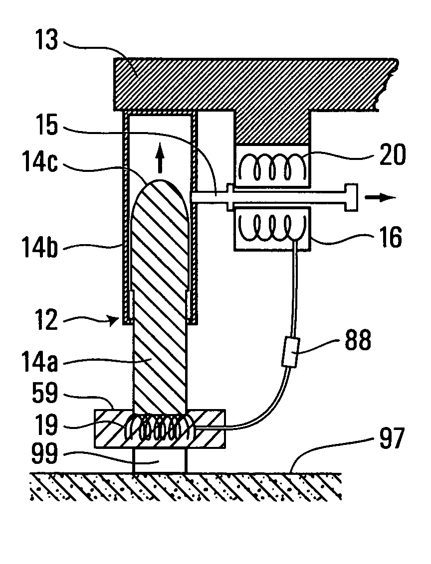
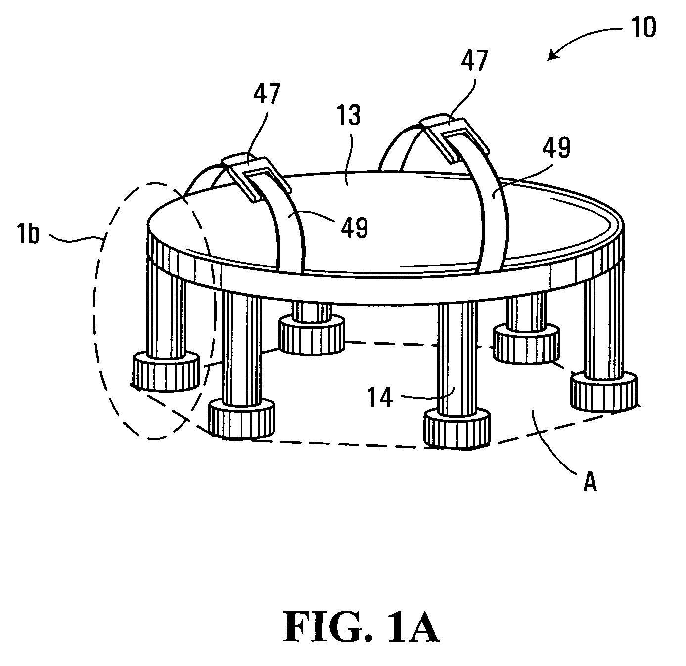
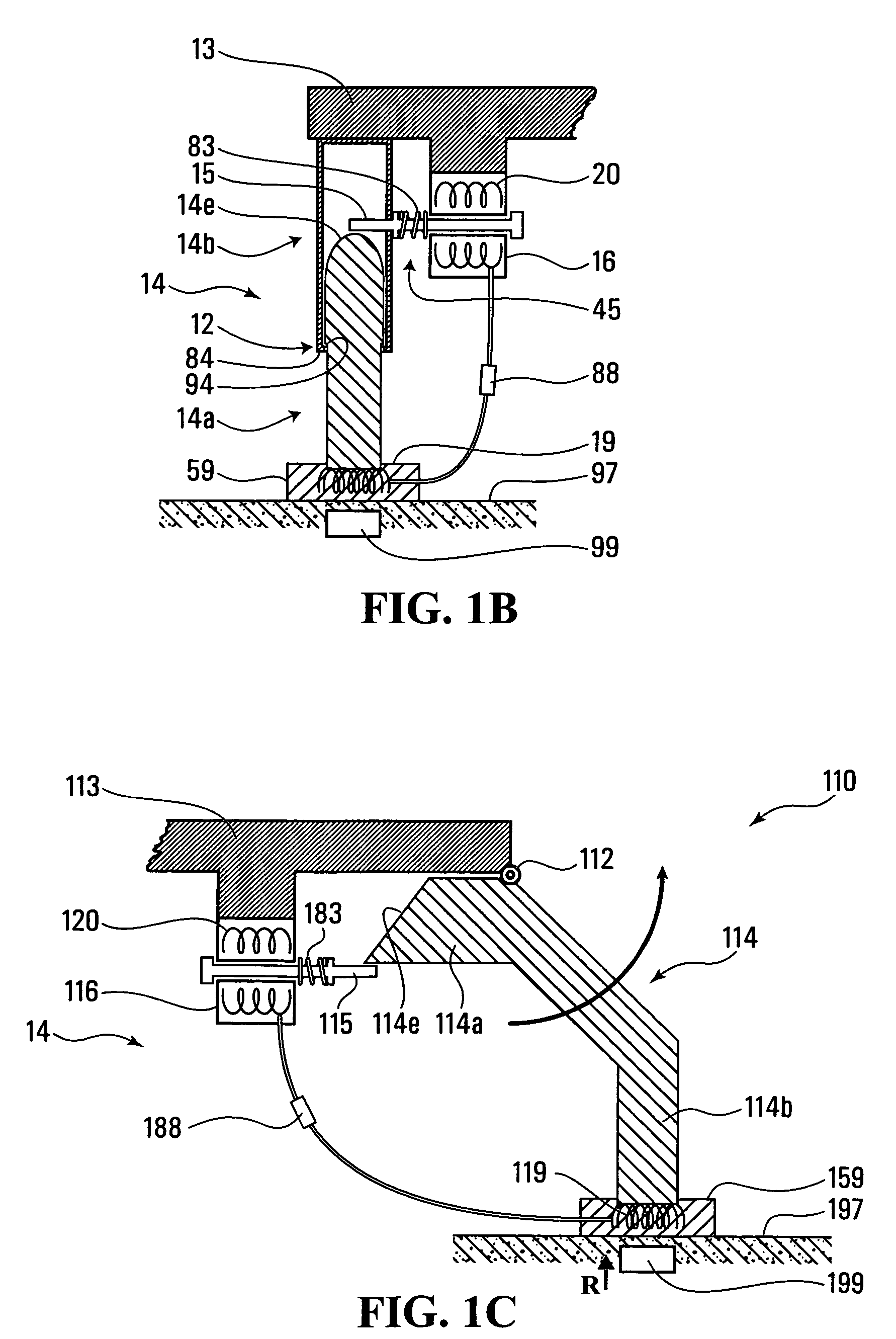
[0045]With reference first to FIG. 1a, a mine protection and avoidance device generally designated 10 includes a frame which can be in the form of a plate 13, support legs 14 and straps 49. The plate 13 can be a wide variety of shapes but serves as a supporting plate for support legs and is suitable for being secured directly or indirectly to an appendage, normally a foot, of a person. A plate could also be configured to be securable to a part of a mechanical or robotic device. In other embodiments the support legs might be directly connected to a load source or to a frame other than a plate. The plate 13 can be formed of any material that is capable of satisfying the load bearing requirements, but may be made of a material which would provide some significant level of protection should a mine explode underneath the plate 13. Suitable materials include but are not limited to steel, kevlar and other metals such as by way of example only, aluminium.

[0046]Plate 13 may be constructed wi...


PUM


Abstract

A mine avoidance and protection device has a frame adapted to be secured to a source of a load, such as the foot of a person. Attached to the frame are at least three support legs each extending from the frame. Each leg has a releasable joint between the leg and the frame. At least one detector is operable to provide a detection capability for each support leg, operable to detect a characteristic of a mine when at least a portion of the support leg is located proximate to the mine. An actuator operable to provide an actuation capability at the joint of each leg, to: constrain the joint to allow a load to be transmitted from the frame, through the joint and the support to the terrain. The actuator can also release the joint such that a load can not be transmitted from the frame through the joint. The joint between the plate and each leg may be a one degree-of-freedom prismatic joint or revolute joint.

Description

FIELD OF THE INVENTION[0001]The invention relates to landmine avoidance and protection devices, including landmine avoidance and protection footgear.BACKGROUND OF THE INVENTION[0002]Mines are devices, which are designed to explode when they are either touched by, or come into close proximity with, an object, such as a vehicle or human beings, causing damage to the object. Landmines are mines which are situated in or on ground terrain. Anti-personnel (AP) landmines are landmines that are specifically designed to harm human beings who are walking or otherwise moving across ground terrain. Mines targeted primarily at vehicles like tanks and troop carriers typically have a diameter in the range of about 20-40 cm. AP mines are typically smaller having for example, a diameter in the range of about 4.5-15 cm. AP mines are often deployed over a large area and are usually buried in the ground or otherwise camouflaged.[0003]The clearing of existing minefields requires special protection for p...

Claims


Application Information

Patent Timeline
Patent Type & Authority Patents(United States)
IPC IPC(8): F41H11/12
CPCA43B1/0054A43B3/0005A43B3/0026F41H1/00F41H11/136F41H11/13A43B3/34
Inventor FUSS, FRANZ KONSTANTINTAN, MING ADIN
Owner NANYANG TECH UNIV
Why Eureka
Try Eureka