
Fuel injection system

a fuel injection system and fuel injection pump technology, applied in the direction of fuel injection pumps, liquid fuel feeders, machines/engines, etc., can solve the problems of air dissolved in the fuel to outgas, the fuel injection system is absolutely fluid-tight, and the start delay to occur, so as to reduce the length of the line

Inactive Publication Date: 2008-10-21
ROBERT BOSCH GMBH
View PDF8 Cites 8 Cited by
  • Summary
  • Abstract
  • Description
  • Claims
  • Application Information

AI Technical Summary

Benefits of technology

The present invention relates to a fuel injection system for an internal combustion engine that has a low-pressure region and a high-pressure region. The system includes a check valve device that prevents negative pressure in the high-pressure region and delays in starting the engine. The check valve device has a high-pressure inlet, a high-pressure outlet, and a low-pressure connection, and can be integrated into existing fuel injection systems without modification. The check valve device can be designed to eliminate negative pressure and can be mounted at various locations in the system. The technical effect of the invention is to improve the starting performance of the engine and to prevent fuel leakage during starting.

Problems solved by technology

As a result, the fuel injection system is absolutely fluid-tight when the engine is not running.
If there is a large temperature difference between when the engine is switched off and when it is restarted, then the fluid-tightness of the high-pressure region and the temperature-induced contraction of the fuel volume contained therein causes the air dissolved in the fuel to outgas.
When starting, the outgassed air can cause the above-mentioned starting delay to occur.

Method used


Image

  • Fuel injection system
  • Fuel injection system
  • Fuel injection system

Examples


Embodiment Construction

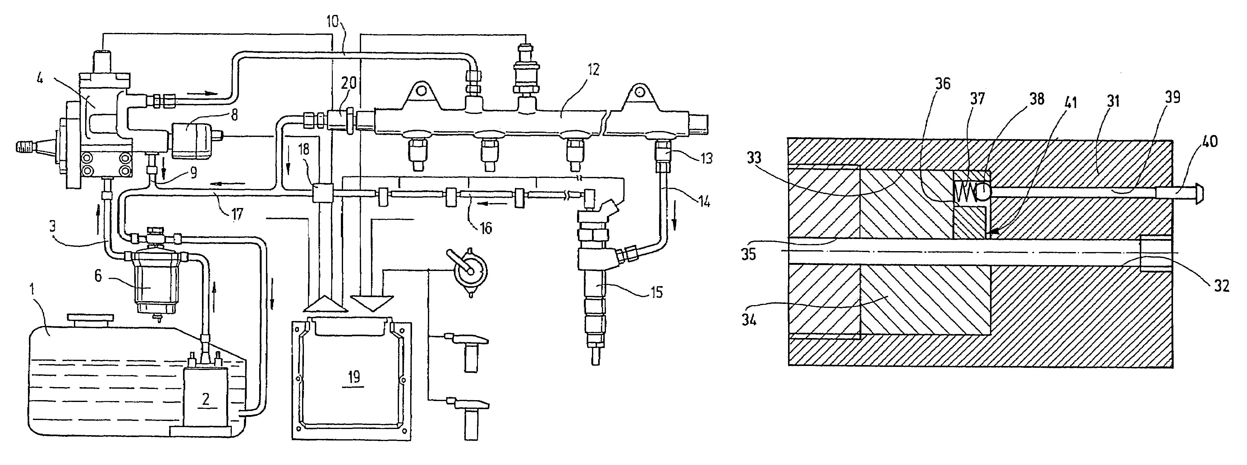
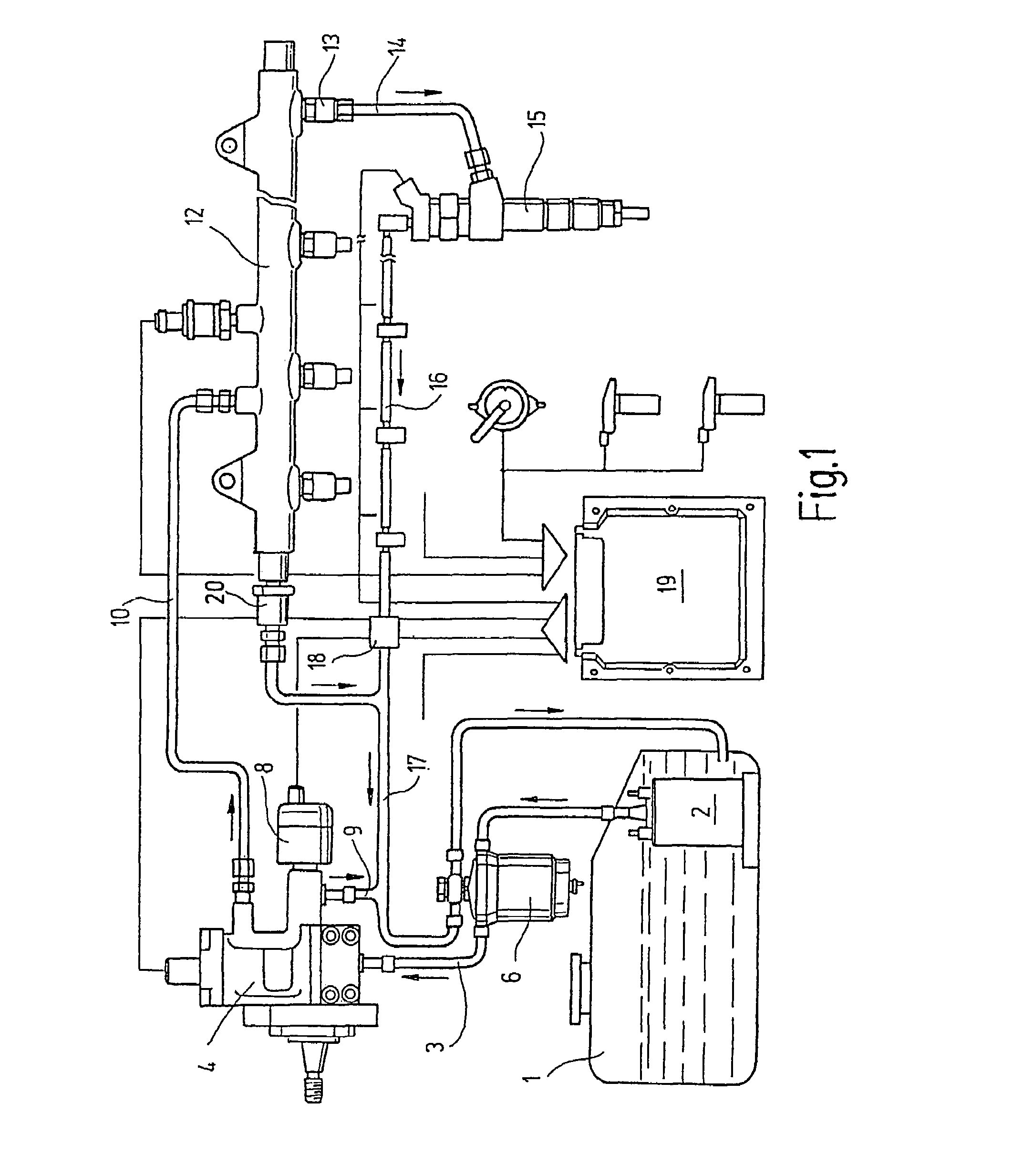
[0024]FIG. 1 schematically depicts a conventional common rail fuel injection system. From a low-pressure reservoir 1, which is also referred to as the fuel tank, a fuel supply pump 2 delivers fuel to a high-pressure pump 4 via a connecting line 3. The connecting line 3 contains an overflow valve 6. The low-pressure reservoir 1, the fuel supply pump 2, and the connecting line 3 are acted on with low pressure and are therefore referred to as the low-pressure region.

[0025]The high-pressure pump 4 is connected to a pressure control valve 8, which is connected to the low-pressure reservoir 1 via a line 9. In addition, a high-pressure line 10 leads from the high-pressure pump 4 and supplies the highly pressurized fuel to a high-pressure fuel accumulator 12, which is also referred to as a common rail. High-pressure lines 14 lead from the high-pressure accumulator 12 via interposed flow limiters 13 and deliver the highly pressurized fuel from the high-pressure accumulator 12 to injection va...


PUM


Abstract

A common rail fuel injection system having a low-pressure region from which a high-pressure fuel pump acts on fuel with high pressure and delivers it to a high-pressure fuel accumulator from which fuel is supplied to injectors that inject the highly pressurized fuel into the combustion chamber of an internal combustion engine in which the high-pressure pump, the high-pressure fuel accumulator, and the injectors are associated with a high-pump, pressure region. In order to avoid undesirable delays in the starting of the internal combustion engine, a check valve device is connected between the low-pressure region and the high-pressure region so that when a negative pressure is generated in the high-pressure region, fuel flows from the low-pressure region into the high-pressure region.

Description

CROSS-REFERENCE TO RELATED APPLICATION[0001]This application is a 35 USC 371 application of PCT / EP 2005 / 052663 filed on Jun. 9, 2005.BACKGROUND OF THE INVENTION[0002]1. Field of the Invention[0003]The invention relates to a fuel injection system, in particular a common rail system, having a low-pressure region from which a high-pressure fuel pump acts on fuel with high pressure and delivers it to a high-pressure fuel accumulator from which fuel is supplied to injectors that inject the highly pressurized fuel into the combustion chamber of an internal combustion engine in which the high-pressure pump, the high-pressure fuel accumulator, and the injectors are associated with a high-pressure region.[0004]2. Prior Art[0005]Conventional fuel injection systems can have design-based leaks. For example, the injectors can represent leak points. The leakage quantity can be compared to a temperature-induced contraction of the fuel volume contained in the system. In special fuel injection syste...

Claims


Application Information

Patent Timeline
Patent Type & Authority Patents(United States)
IPC IPC(8): F02M37/00F02M37/10F02M59/46F02M63/02
CPCF02M63/0012F02M63/0225F02M2200/60
Inventor SCHEURER, HANS-PETERSTEINBACH, TIMO
Owner ROBERT BOSCH GMBH
Learn More