Methods and connections for coupled pipe

a technology of coupled pipes and connections, applied in the field of methods and connections, can solve the problems of reducing the central clearance through the connector, reducing the clearance through the coupling, and reducing the coupling clearance, and achieve the effect of inexpensive manufacturing

Active Publication Date: 2008-10-21
VAM USA
View PDF20 Cites 15 Cited by
  • Summary
  • Abstract
  • Description
  • Claims
  • Application Information

AI Technical Summary

Benefits of technology

[0015]The present invention successfully incorporates the benefits of individual prior art design features in a new assembly within a single connection to achieve an economic, effective high-pressure thread seal that is inexpensively manufactured using standard coupling stock and assembled with final make-up torque values within the capacity of rig site tongs and having the ability to function leak free within testing or working environments in which the connection is exposed to high axial stress loads. These beneficial results are achieved without the benefit of a metal-to-metal seal or a supplementary O-ring seal.

Problems solved by technology

In addition to being more costly, thick wall coupling designs reduce the central clearance through the connector.
Coupling strength may be obtained by increasing the wall thickness toward the center of the coupling, however such strengthening results in reducing the clearance through the coupling.
Reduced coupling clearance is usually associated with an undesirable reduction in the clearance through the pipe engaged in the coupling.
This micro-movement disturbs the thread compound in conventional thread designs and can lead to the initiation of leaks.
Increasing the final torque is not necessarily an economical option for increasing the preload in an attempt to overcome this susceptibility to leakage.
In addition to the fact that the rig tongs may often lack capacity to add sufficient final torque, very high torque values applied to the pipe increase the opportunity to damage the pipe body and / or the pipe threads.
None of the prior art, however, teaches or suggests an easily manufactured, economical connection that provides a satisfactory thread seal in conventional coupling stock within an environment subjected to high axial stress loads with final make-up torques that are within the working capacity of the power tongs commonly used to assemble connections at the well site.

Method used


Image

  • Methods and connections for coupled pipe
  • Methods and connections for coupled pipe
  • Methods and connections for coupled pipe

Examples


Embodiment Construction

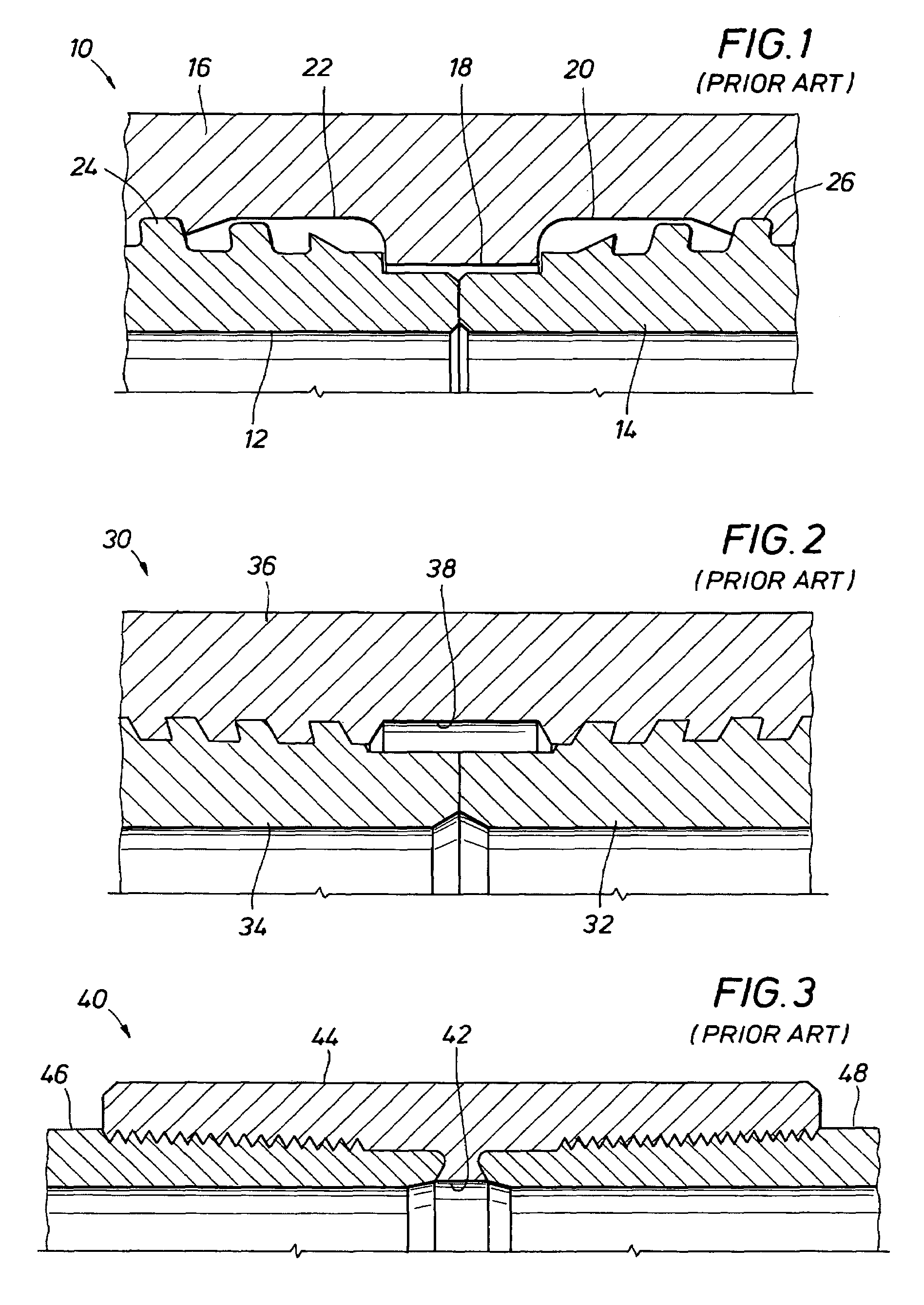
[0046]FIG. 1 illustrates a prior art connector, indicated generally at 10, in which pins 12 and 14 are connected within a coupling 16. The two pins 12 and 14 engage at noses formed at their axial ends to form mutual torque shoulders. The central portion of the coupling 16 includes a centrally enlarged area 18 that functions as a mill make-up arrester and provides coupling strength at the center of the coupling. Recessed areas 20 and 22 on either axial side of the enlarged area 18 are devoid of threads such that the pin noses of the pins 12 and 14 are free to be axially stressed without transferring axial stress to the surrounding coupling 16. Threads 24 on the pin 12 and 26 on the pin 14 engage the internal coupling threads to provide a mechanical engagement and thread seal. The threads 24 and 26 are provided with negative load flanks to impart radially compressive forces between the pin threads and the coupling.

[0047]The design of the prior art connection of FIG. 1 requires that th...


PUM


Abstract

A threaded and coupled connector with tapered threads having equivalent heights (same height on pin and box threads), negative load flanks, biased tapered thread forms with a torque shoulder formed by pin noses that abut at a central point within a coupling constructed from standard coupling stock. The connection design meets the internal / external pressure performance requirements of industry standards with capabilities equal to or exceeding those of “premium” connections, with a coupling constructed from thin walled coupling stock.

Description

BACKGROUND OF THE INVENTION[0001]1. Field of the Invention[0002]The present invention relates to methods and connections for securing together the ends of threaded tubular bodies to produce a structurally strong and leak resistant joinder of such tubular bodies. More specifically, the present invention relates to a threaded coupling and pin assembly, and associated method, for securing together the threaded ends of tubular pipe bodies such that the engaged pin and coupling threads will form a secure mechanical engagement and a high-pressure, leak resistant thread seal.[0003]2. Background Setting of the Invention[0004]Tubular pipe bodies used in the construction of oil and gas wells are typically secured together at their ends by threaded connectors that employ a thread and seal design intended to withstand the structural forces acting between the threaded components as well as to prevent the flow of high-pressure well fluids through the engaged threads of the connection. In many of ...

Claims


Application Information

Patent Timeline
Patent Type & Authority Patents(United States)
IPC IPC(8): F16L25/00
CPCE21B17/042F16L15/001
Inventor DELANGE, RICHARD W.HEGLER, MATTHEW ALLENBAILEY, ANDYLE GREGORY
Owner VAM USA
Why Eureka
Try Eureka