Anti-Decoupling device for a spin coupling

Inactive Publication Date: 2008-10-21
LOCKHEED MARTIN CORP
View PDF10 Cites 17 Cited by
  • Summary
  • Abstract
  • Description
  • Claims
  • Application Information

AI Technical Summary

Benefits of technology

[0007]The present invention provides a way to prevent a spin coupling fro

Problems solved by technology

Inadvertent rotation can result, for example, from shock, vibration, G-loading, e

Method used


Image

  • Anti-Decoupling device for a spin coupling
  • Anti-Decoupling device for a spin coupling
  • Anti-Decoupling device for a spin coupling

Examples


Embodiment Construction

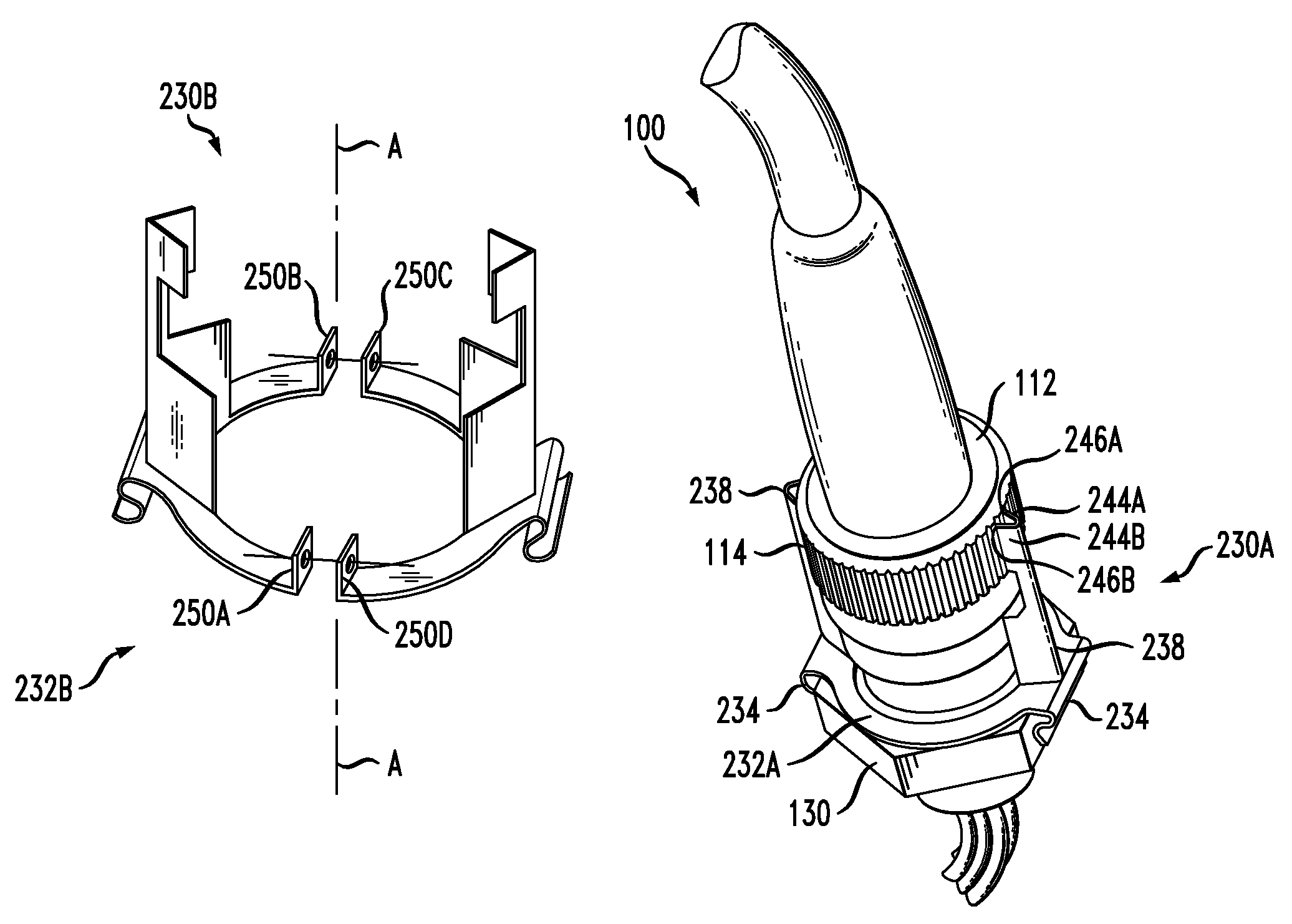
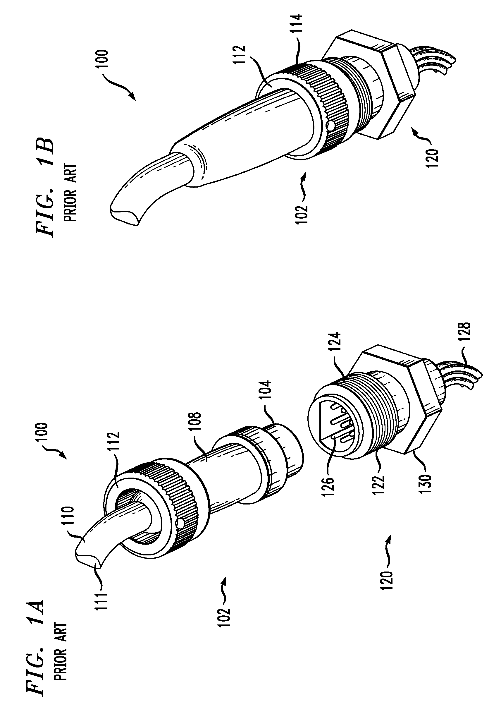
[0027]FIGS. 1A and 1B depict, via perspective views, the salient elements of a conventional, two-part electrical connector 100. FIG. 1A depicts connector 100 in a disconnected state and FIG. 1B depicts connector 100 in a connected state.

[0028]As depicted in FIG. 1A, a female connector portion 102 of connector 100 includes body 104, cable strain relief 108, sheath 110, and spin coupling 112, interrelated as shown. Electrical conductors 111 are disposed in sheath 110 and terminate, at body 104, in sockets (not depicted).

[0029]Male connector portion 120 of connector 100 includes body 122, screw threads 124, contact pins 126, electrical conductors 128, and hex mount 130, interrelated as shown. Pins 126 are electrically connected to conductors 128.

[0030]To electrically connect electrical conductors 128 to electrical conductors 111, female connector portion 102 and male connector portion 120 are pushed together into mating engagement. In this state, pins 126 are received by the sockets wi...


PUM


Abstract

An anti-decoupling device for use in preventing undesired rotation of a spin coupling of, for example, a two-part electrical connector, is disclosed. The anti-decoupling device can form part of a new connector, or can be used to retrofit existing connectors without having to modify the connector. In some embodiments, the anti-decoupling device comprises a base and two prongs that extend in a generally axial direction relative to the base. Blades that depend from the prongs extend into channels within the knurled side-edge of the spin coupling. The blades prevent inadvertent rotation of the spin coupling.

Description

FIELD OF THE INVENTION[0001]The present invention relates to connectors, and, more particularly, to a device that prevents a spin coupling from loosening.BACKGROUND OF THE INVENTION[0002]It is common practice to use a two-part connector to join electrical conductors. In such connectors, a first group of electrical conductors terminate in one of the connector “halves” and a second group of electrical conductors terminate in the other of the connector halves. To establish electrical connection between the two groups of electrical conductors, the two connector halves are joined.[0003]The two halves of the connector are typically held together by a nut, typically referred to as a “spin coupling,” a “coupling nut,” or a “locking ring.” The spin coupling is usually permanently attached to one of the connector halves at the time of initial assembly. In some embodiments, the spin coupling is internally threaded and is rotated to engage mating threads on the other connector half.[0004]The sp...

Claims


Application Information

Patent Timeline
IPC IPC(8): H01R13/62
CPCH01R13/622H01R13/639
Inventor PELLEN, ALAIN T.
Owner LOCKHEED MARTIN CORP
Why Eureka
Try Eureka