Card connector

a card connector and connector technology, applied in the direction of coupling contact members, coupling device connections, instruments, etc., can solve the problems of inability to provide the card with an appropriate friction force, plastic deformation of the contact piece, and the need for contact pressure cannot be given to the contact terminal, so as to prevent the card from falling out of the connector. , the effect of holding the card steady and reliably

Inactive Publication Date: 2008-10-21
PANASONIC CORP
View PDF156 Cites 9 Cited by
  • Summary
  • Abstract
  • Description
  • Claims
  • Application Information

AI Technical Summary

Benefits of technology

[0031]Hence, if the first card is erroneously inserted upside down, the lower body portion of the first card can escape upward through the opening or recess, making it possible to give the braking piece the same displacement as during the normal insertion and thereby prevent the braking piece from being deformed or displaced in excess of its stress limit.
[0032]In a further aspect of the invention, because the elastic braking piece is pressed against the equal-thickness portions of the first and second cards with different thicknesses, the same braking force can be applied to the first and second cards with different thicknesses in the card retraction direction during the card insertion process. Hence, either of the cards can be held stably and reliably, preventing the card from falling out from the connector due to unexpected external forces.

Problems solved by technology

Hence, if the elastic force (contact pressure) of the contact terminals is set to conform to a thicker card, a required contact pressure cannot be given to the contact terminals when a thinner card is inserted.
Conversely, if the contact pressure of the contact terminals is set to conform to a thinner card, when a thick card is inserted, the contact terminals deflect excessively beyond the stress limit, resulting in plastic deformations of the contact pieces.
Hence, if the elastic displacement (contact pressure) of the braking piece is set to produce an appropriate friction force for the thick card, the contact pressure and the resulting frictional force are too small for the thin card, making it impossible to provide the card with an appropriate friction force.
Conversely, if the elastic displacement (contact pressure) of the braking piece is set to produce an appropriate friction force for the thin card, the insertion of a thick card causes the braking piece to deflect excessively beyond the stress limit, resulting in the braking piece being plastically deformed.

Method used


Image

  • Card connector
  • Card connector
  • Card connector

Examples


first embodiment

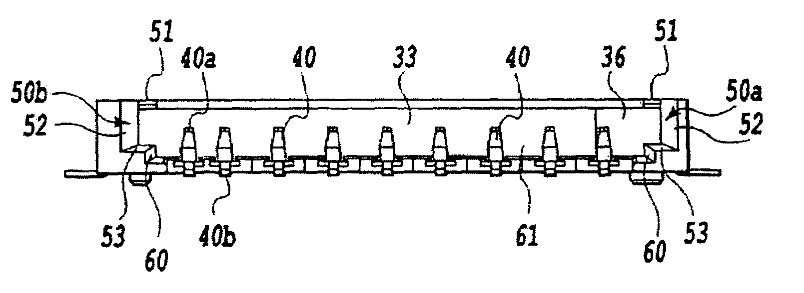
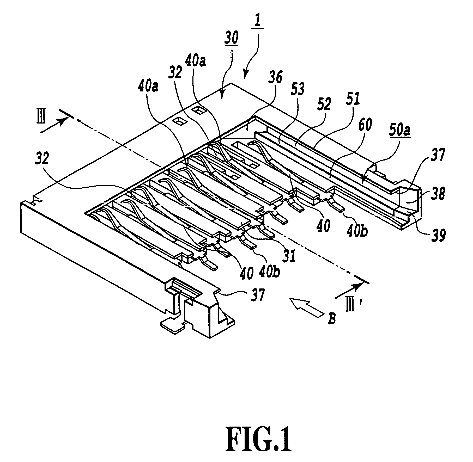
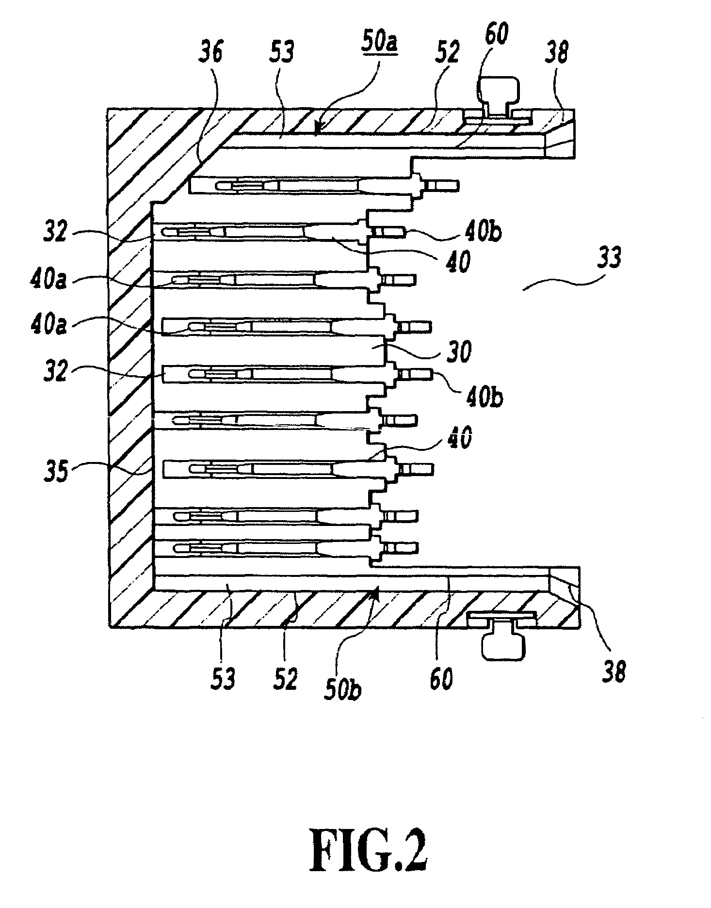
[0053]FIG. 1 is a perspective view showing a card connector according to the first embodiment of this invention. FIG. 2 is a horizontal cross section of the card connector. FIG. 3 is a cross section taken along the line III-III of FIG. 1. FIG. 4 is a front view of the card connector as seen from the direction of arrow B in FIG. 1.

[0054]The card connector 1 is mounted on an electronic device, such as cellular phone, PDA, portable audio device and camera.

[0055]The connector 1 shown in FIG. 1 to FIG. 4 can accommodate both a thin card 10 such as an MMC card shown in FIG. 16 and FIG. 17 and a double-height thick card 20 with step portions such as an SD card shown in FIG. 18 and FIG. 19.

[0056]In FIG. 1 to FIG. 4, the card connector 1 has a connector housing 30 roughly U-shaped when viewed from above and which is made from an insulating material such as resin and formed in one piece having side leg portions.

[0057]A base plate 31 of the connector housing 30 is formed with a plurality of pr...

second embodiment

[0073]Next, the second embodiment of the present invention will be described by referring to FIG. 8 to FIG. 14.

[0074]FIG. 8 is a plan view showing a card connector according to the second embodiment of this invention. FIG. 9 is a front view of the card connector as seen from a direction of arrow B in FIG. 8. FIG. 10 is a partly cutaway plan view of the card connector.

[0075]The connector 1 shown in FIG. 8 to FIG. 10 can accommodate both a thin card 10 such as an MMC shown in FIG. 16 and FIG. 17 and a double-height thick card 20 with step portions such as an SD card shown in FIG. 18 and FIG. 19. Components with the same functions as those of the first embodiment are assigned like reference numbers to facilitate the understanding of the second embodiment.

[0076]In FIG. 8 to FIG. 10, a base plate 31 of the connector housing 30 is formed with a plurality of press-fit grooves 32 in which a plurality of contact terminals 40 made from contact leaf springs are fitted under pressure. The conta...


PUM


Abstract

The connector housing 30 is formed with a pair of guide grooves 50a, 50b and a pair of side walls 60. The guide grooves 50a, 50b support the both side edges of the upper body portion 21 of the thick first card 20 and also the both side edges of the card body 11 of the thin second card 10 and guide these cards as they are inserted or extracted. The side walls 60 define, below a space between the paired guide grooves 50a, 50b, a space in which to accommodate the lower body portion 23 of the first card 20. This construction ensures that, whichever of the first and second cards is inserted, the elastic displacements of the contact terminals 40 of a card connector 1 remain the same, allowing the card to be electrically connected stably.

Description

TECHNICAL FIELD[0001]The present invention relates to a card connector structure mounted on electronic devices, such as cellular phones, telephones, PDAs (personal digital assistants), portable audio devices and digital cameras, and more specifically to a card connector into which two kinds of cards with different thicknesses can suitably be inserted. The present invention also relates to a card connector capable of preventing the card from falling from the card connector when it is ejected.BACKGROUND ART[0002]In electronic devices such as cellular phones, telephones, PDAs and digital cameras, a variety of functions are added by inserting an IC card with a built-in memory or control IC, such as a SIM (subscriber identity module) card, an MMC (multimedia card), a Smart Media (trademark), an SD (super density or secure digital) card and a Memory Stick (trademark).[0003]As the number of kinds of IC cards has increased in recent years, a variety of standards as to the card thickness hav...

Claims


Application Information

Patent Timeline
Patent Type & Authority Patents(United States)
IPC IPC(8): H01R24/00G06K7/00H01R13/24H01R27/00
CPCG06K7/0021H01R13/2442H01R27/00H01R12/721G06K7/00
Inventor ITO, TOSHIYASUOYA, MASAAKITAGUCHI, KAZUTAKATORII, TAKASHIKAWAI, HIDEKI
Owner PANASONIC CORP
Why Eureka
Try Eureka