
Foot switch for activating a dental or medical treatment apparatus

a technology for medical treatment and foot switch, which is applied in contact mechanisms, dental surgery, surgery, etc., can solve problems such as potential safety hazards and operator feeling uncomfortable sensations

Active Publication Date: 2008-10-21
DENTSPLY SIRONA INC
View PDF29 Cites 95 Cited by
  • Summary
  • Abstract
  • Description
  • Claims
  • Application Information

AI Technical Summary

Benefits of technology

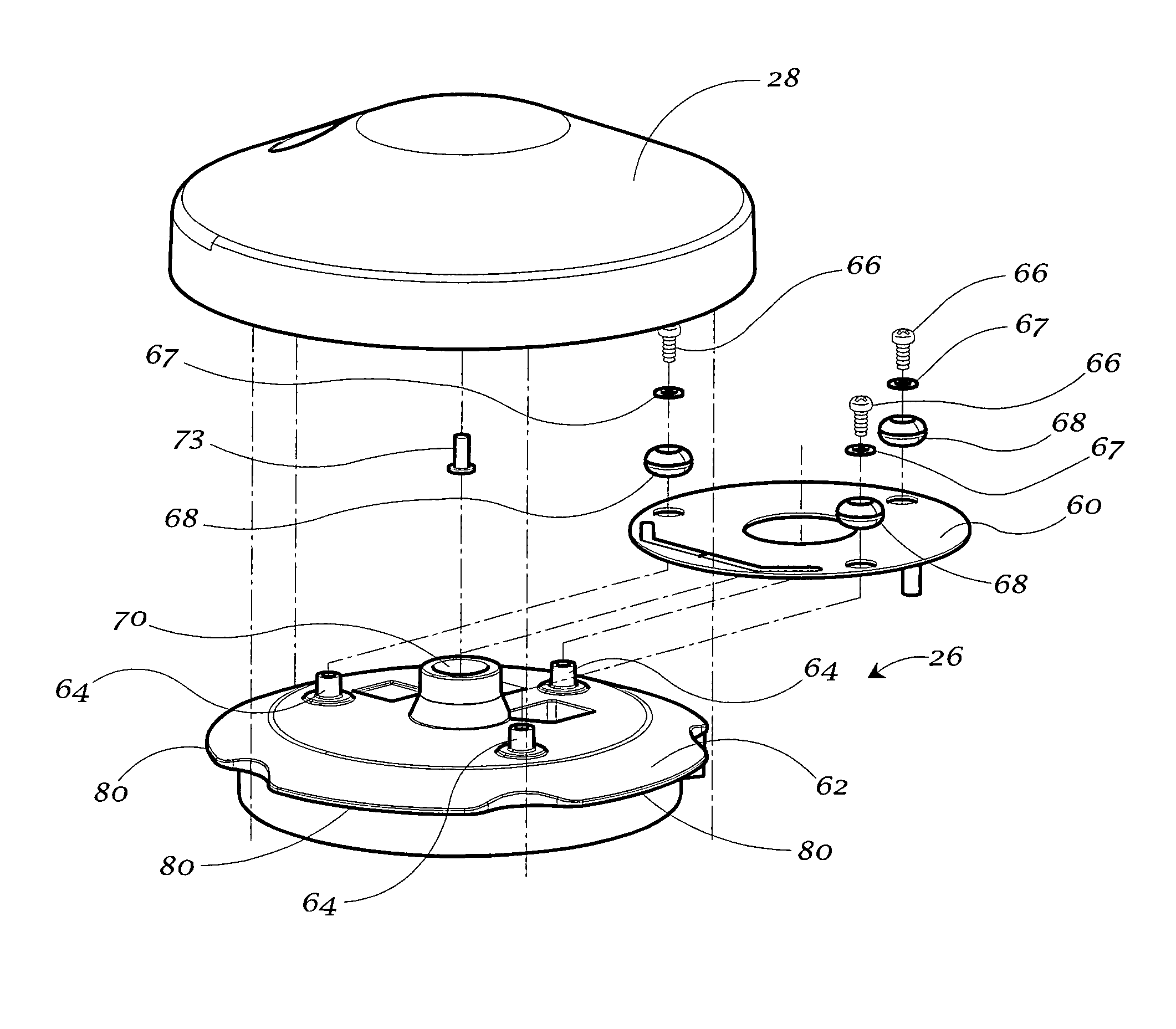
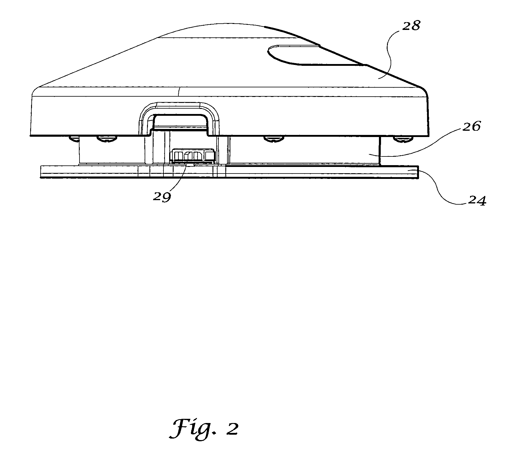
"The present invention is about a foot switch device used to control the operation of dental or medical treatment apparatuses. The foot switch device includes a base plate, a central housing, an upper cover, and a connecting collar. The central housing contains two electrical switches and an actuator assembly for activating the switches. The actuator assembly includes an actuating plunger, a first switch activator tab, and a second switch activator tab. The upper cover is pressed with the foot to activate the plunger, which then moves to engage the first or second switch activator tab to activate the corresponding switch. The foot switch device can be used to control the operation of a dental treatment apparatus, such as an ultrasonic dental scaler, in a wireless or hard-wired system. The first mode of operation is normal ultrasonic scaling power, and the second mode is boosted ultrasonic scaling power. The technical effect of this invention is to provide a convenient and efficient way to control the operation of dental or medical treatment apparatuses with a foot switch device."

Problems solved by technology

Thirdly, as mentioned above, some conventional foot switches are used in wireless systems, which do not run a connector cable between the foot switch and base unit.
The entangled cords and cables take up space and may cause potential safety hazards.
Consequently, an operator may feel an uncomfortable sensation while pressing the cover with his or her foot.

Method used


Image

  • Foot switch for activating a dental or medical treatment apparatus
  • Foot switch for activating a dental or medical treatment apparatus
  • Foot switch for activating a dental or medical treatment apparatus

Examples


Embodiment Construction

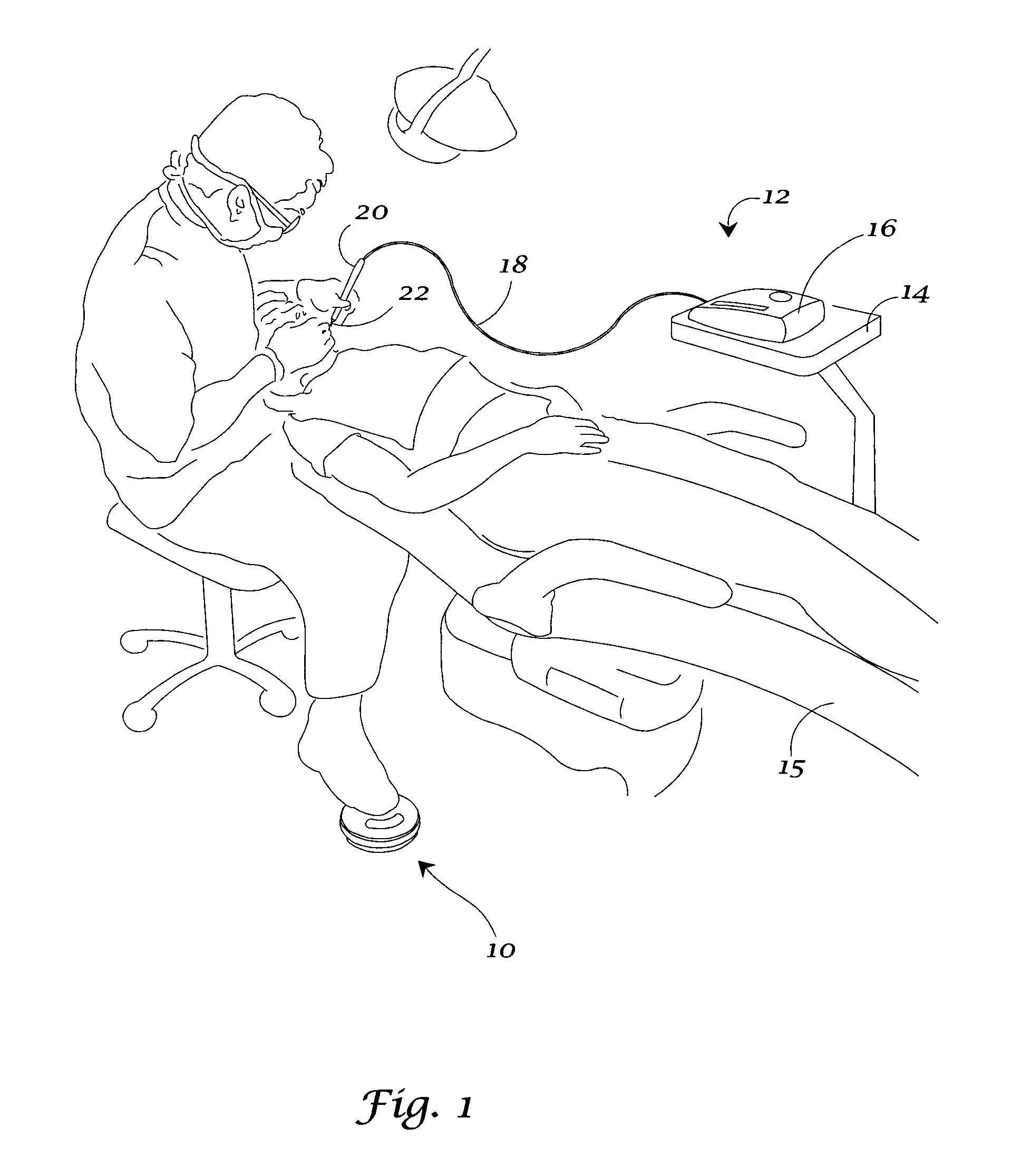
[0034]Referring to the drawings, FIG. 1 illustrates one embodiment of the foot switch device (10) of the present invention. In FIG. 1, a dental professional is shown pressing the foot switch device (10) in order to activate a dental treatment apparatus, particularly an ultrasonic dental scaler unit (12), which is seated on a tray (14) attached to a dental chair (15). Dental professionals use ultrasonic dental scalers (12) to provide therapeutic and preventive care to their patients. The ultrasonic scaler (12) is used primarily to remove calculus deposits and plaque from tooth surfaces. The ultrasonic dental scaler (12) includes a base power unit (16). A flexible and lightweight cable (18) connects a handpiece (20) to the base unit (16). A power scaling insert (22) is inserted into the handpiece (20). Different scaling inserts (22) are used depending upon the health of the patient, the tooth to be treated, and the type of deposits to be removed. The scaling insert (22) is based on ma...


PUM


Abstract

A foot switch device for activating a dental or medical treatment apparatus is provided. The foot switch device is particularly suitable for controlling an ultrasonic dental scaler. The foot switch device includes a base plate; a central housing attached to the base plate; an upper, moveable cover mounted on the housing; and a connecting collar attached to the upper cover for retaining the cover on the housing while allowing the cover to move upwardly and downwardly relative to the housing. The central housing contains a first electrical switch for transmitting a first signal to the apparatus, and a second electrical switch for transmitting a second signal to the apparatus. An operator depresses the upper cover with his or her foot to activate the switching mechanism and control the operation of the dental or medical apparatus.

Description

BACKGROUND OF THE INVENTION[0001]1. Field of the Invention[0002]The present invention relates generally to a foot switch device used for activating a dental or medical treatment apparatus. More particularly, the invention relates to a two-stage foot switch device having an upper moveable cover. An operator depresses the cover with his or her foot to activate the switching mechanism in the foot switch device. The switching mechanism controls the operation of the dental / medical apparatus. The foot switch device is particularly suitable for operating an ultrasonic dental scaler.[0003]2. Brief Description of the Related Art[0004]Today, dental and medical professionals use many instruments that are controlled by foot control systems. For example, surgical cutting instruments, endoscopic tools, irrigation and aspiration tools, dental drills and other handpieces, ultrasonic dental scalers, and dental prophylaxis units can be activated with foot control systems. The foot control system typi...

Claims


Application Information

Patent Timeline
Patent Type & Authority Patents(United States)
IPC IPC(8): H01H9/06
CPCA61C1/0023H01H3/14A61B2017/00973H01H2225/018A61C17/20H01H25/04
Inventor BRENNER, TODLINT, KEVIN
Owner DENTSPLY SIRONA INC
Learn More