Unlock instant, AI-driven research and patent intelligence for your innovation.

Image-taking apparatus and optical adjustment method for an image-taking apparatus with displacement of the optical axis

an image-taking apparatus and optical adjustment technology, applied in the field of image-taking apparatuses, can solve the problems of image-taking apparatus becoming larger, image-picking element being unbalanced as to the light amount of four peripheral parts,

Inactive Publication Date: 2008-10-21
CANON KK
View PDF7 Cites 8 Cited by
  • Summary
  • Abstract
  • Description
  • Claims
  • Application Information

AI Technical Summary

Benefits of technology

The present invention provides an image-taking apparatus and an optical adjustment method that can adjust the position displacement between the image-taking optical system and the image-pickup element even after assembly is completed. This allows for precise and accurate image capture even when the object being photographed is not perfectly aligned with the image-taking optical system. The optical adjustment method involves adjusting the position of the offset lens unit in the image-taking optical system to ensure that light amounts in peripheral parts on the image-pickup element are balanced, and preventing the object point image-formed at the center on the image-pickup element from moving during variations in magnification. This results in a more stable and high-quality image capture.

Problems solved by technology

There are many cases, however, where an optical axis of the image-taking lens system is slightly displaced from a center of the image-pickup element due to a manufacturing error and the like.
Therefore, if the center of the image-pickup element is displaced from the optical axis of the image-taking lens system, there arises unbalance as to the light amount of four peripheral parts (in the vicinity of four corner parts) on the image-pickup element.
Therefore, it is necessary to provide a space to move the image-pickup element unit in the image-taking apparatus, and so there is a problem that the image-taking apparatus becomes larger-size.
In addition, the image-pickup element is fixed (attached) on the image-taking lens system by adjusting its position, and so positioning work is cumbersome.

Method used


Image

  • Image-taking apparatus and optical adjustment method for an image-taking apparatus with displacement of the optical axis
  • Image-taking apparatus and optical adjustment method for an image-taking apparatus with displacement of the optical axis
  • Image-taking apparatus and optical adjustment method for an image-taking apparatus with displacement of the optical axis

Examples


embodiment 1

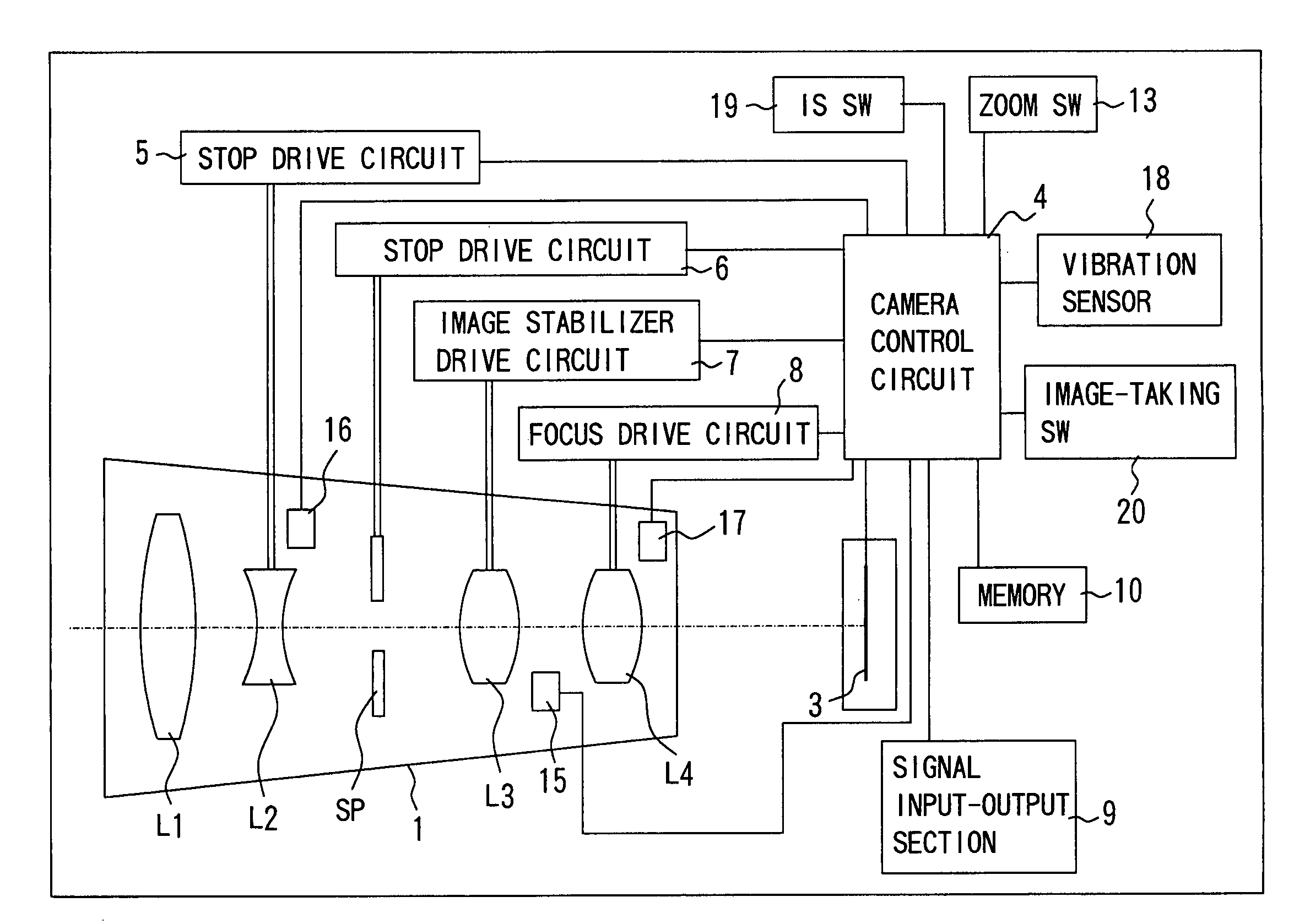
[0031]FIG. 1 is a block diagram showing a structure of a video camera (image-taking apparatus) which is Embodiment 1 of the present invention. In FIG. 1, reference numeral 1 denotes a zoom image-taking lens system (image-taking optical system capable of variation of magnification). The image-taking lens system 1 is comprised of, from an object side (left side in the drawing) to an image surface side, a positive fixed lens unit L1, a negative variator lens unit L2, a stop unit SP, a positive blurring correcting lens unit (hereafter, merely referred to as a correcting lens unit) L3 and a positive compensator and focus lens unit (hereafter, merely referred to as a focus lens unit) L4.

[0032]The variator lens unit L2 moves in an optical axis direction of the image-taking lens unit 1 to perform variation of magnification, and the focus lens unit L4 moves in the optical axis direction to correct image surface movement in conjunction with the variation of magnification and perform focusing....

embodiment 2

[0079]Next, a description will be given as to a zoom center displacement adjustment method for the video camera which is Embodiment 2 of the present invention. The camera to which this adjustment method is applied is the camera of the same structure as described in Embodiment 1, the same components are given the same symbols and the descriptions thereof will be omitted.

[0080]In FIG. 6, reference numeral 100 denotes the camera to which a zoom center displacement adjustment is performed, and 201 denotes a chart (object) and a mark 211 is drawn at its center.

[0081]The signal input-output section 9 of the camera 100 is connected to an adjusting apparatus 202 via the cable 103. And the adjusting apparatus 202 is also connected to the stage 105 via the cable 104.

[0082]Next, an overview of the zoom center displacement adjustment method will be described according to the flowchart in FIG. 7. This flowchart is executed by a controller in the adjusting apparatus 202 (a CPU or the like: hereaf...

embodiment 3

[0109]FIG. 9 shows a control flowchart of the video camera which performs the peripheral light amount adjustment and the zoom center displacement adjustment with a piece of the offset position data in the entire zoom area. This flowchart is mainly executed by the camera control circuit 4.

[0110]First, if the power of the video camera is turned on in Step (abbreviated as S in the drawing) 40, the camera control circuit 4 resets (moves to the reference position for position detection) each lens unit via each drive circuit in Step 41. After this reset operation, the camera control circuit 4 moves the variator lens unit L2 to a zoom position stored in the memory not shown when the power was turned off last time.

[0111]Next, in Step 42, the camera control circuit 4 reads the offset position data stored in the memory 10. And in Step 43, the camera control circuit 4 changes the reference position which is the center of the movement range for correcting the image blurring of the correcting le...


PUM


Abstract

An image-taking apparatus is disclosed which is capable of adjusting a positional displacement of an image-taking optical system and an image-pickup element even in a state in which they are fixed. The image-taking apparatus includes the image-taking optical system including an offset lens unit movable in a direction orthogonal to an optical axis, the image-pickup element and a memory which stores adjustment data. The adjustment data is data on a movement amount of the offset lens unit to make light amounts in peripheral parts on the image-pickup element substantially homogeneous in a case where an object has a surface with approximately homogeneous luminance.

Description

BACKGROUND OF THE INVENTION[0001]1. Field of the Invention[0002]The present invention relates to an image-taking apparatus using an image-pickup element such as a video camera or a digital camera.[0003]2. Description of the Related Art[0004]An image-taking apparatus such as a video camera or a digital still camera has an image-taking lens system and an image-pickup element used therein. There are many cases, however, where an optical axis of the image-taking lens system is slightly displaced from a center of the image-pickup element due to a manufacturing error and the like.[0005]In general, a light amount is reduced as it gets away from an optical axis on an image surface. Therefore, if the center of the image-pickup element is displaced from the optical axis of the image-taking lens system, there arises unbalance as to the light amount of four peripheral parts (in the vicinity of four corner parts) on the image-pickup element.[0006]In the case of using an image-taking lens capable...

Claims


Application Information

Patent Timeline
Patent Type & Authority Patents(United States)
IPC IPC(8): H04N5/228H04N17/00G02B7/02H04N23/40G02B7/04G02B7/10G02B13/18G02B15/16G03B5/00G03B17/02
CPCH04N5/2178H04N5/23212H04N5/23248H04N5/23258H04N5/23287H04N23/673H04N23/68H04N23/6812H04N23/687H04N25/67
Inventor HOSHI, KOJI
Owner CANON KK