Method and an apparatus for shape measurement, and a frequency comb light generator

a frequency comb light and shape measurement technology, applied in the field of shape measurement methods and apparatuses, can solve the problems of time-consuming observation by the system, inability to observe the deep portion inside the measured object, and inability to meet the needs of measurement, etc., and achieve the effect of simple configuration and high stability

Inactive Publication Date: 2008-10-21
NAT UNIV CORP TOKYO UNIV OF AGRI & TECH
View PDF5 Cites 24 Cited by
  • Summary
  • Abstract
  • Description
  • Claims
  • Application Information

AI Technical Summary

Benefits of technology

[0018]Another purpose of the present invention is to provide a frequency COMB light generator which is capable of operation with high stability, variable frequency pitch of frequency COMBs and generation of multiple frequency COMBs by using a simple configuration.

Problems solved by technology

Although the spatial resolution in the depth direction is high in the optical coherence tomography 8, the deep portion inside the measured object O cannot be observed because the light intensity is low and the output level is very low due to the low efficiency.
Furthermore the observation by this system is time consuming and the creditability is not necessarily high because the reference mirror is movable.
However, this type of optical coherence tomography system becomes big and expensive, and therefore it is not suitable for usage in clinics.
However the application of this technique is limited to distance measurement like a fiber-sensing because the frequency pitch cannot be shortened and the number of generated COMBs is limited (See Japanese Patent Application Laid-Open No. 10-148596) and therefore this technique is not suitable for shape measurement like observation of the anatomy under a living body skin.

Method used


Image

  • Method and an apparatus for shape measurement, and a frequency comb light generator
  • Method and an apparatus for shape measurement, and a frequency comb light generator
  • Method and an apparatus for shape measurement, and a frequency comb light generator

Examples


first embodiment

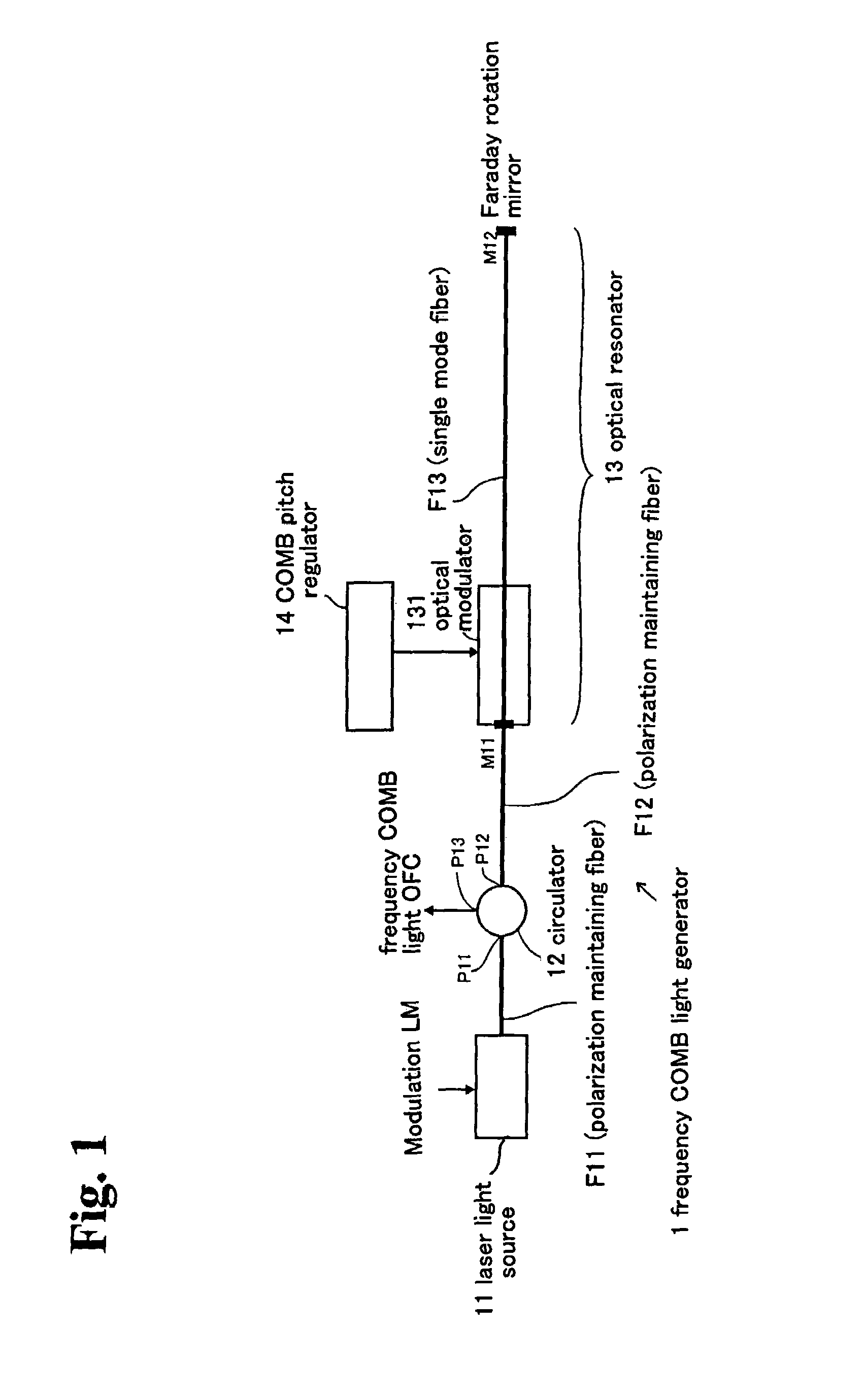
[0031]FIG. 1 is shows a frequency COMB light generator according to the present invention. In FIG. 1, the frequency COMB light generator 1 includes a laser light source 11, a circulator 12, an optical resonator 13 and a COMB pitch regulator 14.

[0032]In this embodiment, the laser light source 11 can output a laser light (center angular frequency ω0) in a wavelength band (e.g. 1.2˜1.6 μm) where the penetration efficiency inside a living body is high.

[0033]In FIG. 1, a modulation signal LM is input into the laser light source 11 and the output of the laser light source 11 can have a predetermined width (e.g. a width from hundreds MHz to GHz) for the center frequency ω0.

[0034]The circulator 12 is located between the laser light source 11 and the optical resonator 13, and the laser light source 11 is connected to a first port P11 through an optical fiber F11 (polarization maintaining fiber) and the optical resonator 13 is connected to a second port P12 through an optical fiber F12 (polar...

second embodiment

[0056]FIG. 5 shows the frequency COMB light generator according to the present invention. In FIG. 5, the frequency COMB light generator 2 includes a laser light source 21, an isolator 22, an optical resonator 23 and a COMB pitch regulator 24.

[0057]The laser light source 21 can output the laser light (center angular frequency ω0) in a wavelength band where the penetration efficiency in a living body is as high as the laser light source 21 in the first embodiment.

[0058]The isolator 22 is located between the laser light source 21 and the optical resonator 23, and the laser light source 21 is connected to a first port P21 through an optical fiber F21 (polarization maintaining fiber) and the optical resonator 23 is connected to a second port P22 through an optical fiber F22 (polarization maintaining fiber).

[0059]The optical resonator 23 generates the frequency COMB light OFC based on the laser light (center frequency ω0) that is output from the laser light source 21. The optical resonato...


PUM


Abstract

A method and an apparatus for shape measurement that is able to observe the deep portion under a skin with high spatial resolution by using a frequency COMB light generator is provided. A frequency COMB light generator for generating multiple frequency COMBs with variable frequency pitch at high operation stability is provided.This apparatus for shape measurement comprises a frequency COMB light generator and an optical interferometer for measuring the distance. The frequency COMB light generator includes a laser light source 11, an optical resonator 13, a COMB pitch regulator 14 and an output port OUT. The optical resonator 13 includes an optical modulator 131, a first mirror M11, an optical fiber F13 which is drawn out from alight waveguide of the optical modulator. The COMB pitch regulator 14 is a modulation signal generator for varying the modulation signal. The optical fiber F13 is equipped with an apparatus (Faraday rotation mirror) for compensating a change in the polarization condition.

Description

TECHNICAL FIELD[0001]This invention relates to a method and an apparatus for shape measurement that is able to observe the deep portion under a skin with high spatial resolution by using a frequency COMB light generator. This invention also relates to a frequency COMB light generator for generating multiple frequency COMBs with variable frequency pitch at high operation stability.BACKGROUND ART[0002]The Optical Coherence Tomography (OCT) is known for obtaining a tomogram of the structure under a skin by applying the light through a living body skin and detecting the reflected light from an internal anatomy) See Japanese Patent Application Laid-Open No. 2004-191114).[0003]FIG. 11(A) shows a prior art an optical coherence tomography system. In FIG. 11(A), an optical coherence tomography system 8 includes a low coherence light source 81, a condensing lens 82, a half-mirror 83, a reference mirror 84, an actuator for moving the reference mirror 85, an object lens 86, a detecting lens 87,...

Claims


Application Information

Patent Timeline
Patent Type & Authority Patents(United States)
IPC IPC(8): G01B9/02
CPCA61B5/0066A61B5/103G01B11/2441A61B2562/0233
Inventor KUROKAWA, TAKASHITANAKA, YOUSUKESHIOTA, TATSUTOSHI
Owner NAT UNIV CORP TOKYO UNIV OF AGRI & TECH
Why Eureka
Try Eureka