Hand tool providing double compound leverage to the jaws

Active Publication Date: 2008-11-04
JANSON PAUL M
View PDF6 Cites 14 Cited by
  • Summary
  • Abstract
  • Description
  • Claims
  • Application Information

AI Technical Summary

Benefits of technology

[0009]The present invention is directed to a hand tool that has an increased mechanical advantage. The hand tool of the present invention includes additional pivots and lever arms that increase the mechanical advantage of

Problems solved by technology

In many applications, the mechanical advantage offered by the simple leverage of three part hand tools is insufficient making it difficult or impossible to achieve the desired result with one hand.
For example, cutting, crimping, and seaming sheet metal with a three part hand snipper, crimper, or seamer can require more hand pressure than the user can deliv

Method used


Image

  • Hand tool providing double compound leverage to the jaws
  • Hand tool providing double compound leverage to the jaws
  • Hand tool providing double compound leverage to the jaws

Examples


Example

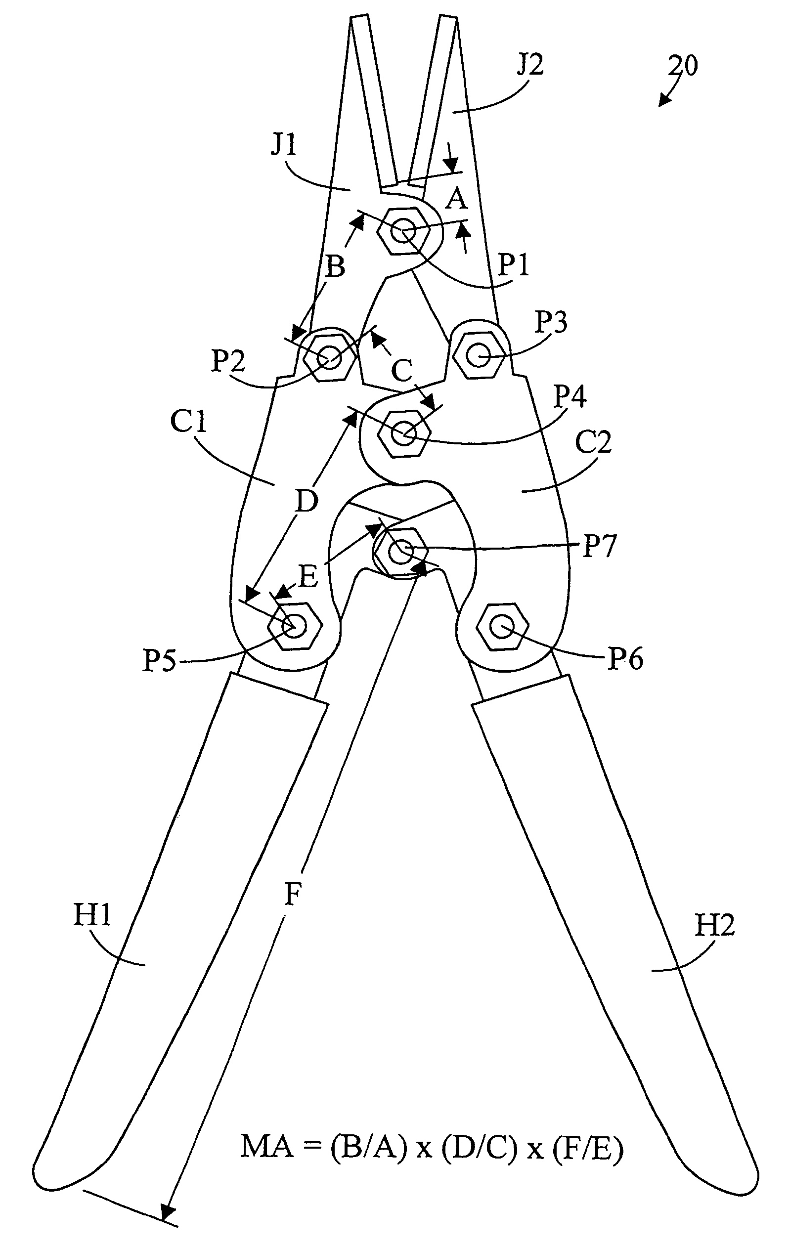
[0018]FIGS. 3 and 4 illustrate side elevation views of a hand tool 20 in accordance with the present invention shown in the open and closed positions, respectively. Hand tool 20 includes a first jaw member J1 and a second jaw member J2. The intermediate portions of jaw members J1 and J2 are pivotally connected at pivot P1. Hand tool 20 also includes first center member C1 and second center member C2. One end of first center member C1 is pivotally connected to first jaw member J1 at pivot P2, and one end of second center member C2 is pivotally connected to second jaw member J2 at pivot P3. The intermediate portions of first center member C1 and second center member C2 are pivotally connected together at pivot P4.

[0019]Hand tool 500 also has first handle member H1 and second handle member H2. An intermediate portion of first handle member H1 is pivotally connected to the opposite end of center member C1 at P5, and an intermediate portion of second handle member H2 is pivotally connect...


PUM


Abstract

A hand tool for use by one hand provides double compound leverage of the force exerted on the handles to the jaws. This is achieved by adding additional pivots and lever arms between the handles and the jaws. The jaws may take the form of a sheet metal snip, seamer, or crimper.

Description

TECHNICAL FIELD[0001]The present invention pertains generally to hand tools, and more particularly to hand tools that are operated using one hand.BACKGROUND OF THE INVENTION[0002]Hand tools having two pivotally connected handles for moving jaws that a user operates with one hand are well known in the art. The basic tool has three parts: a unitary first member having a first handle on one end and a first jaw on the other, a unitary second member having a second handle on one end and a second jaw on the other, and an axle pivotally connecting the two together. Scissors and sheet metal snips are examples of such hand tools operated by one hand.[0003]In many applications, the mechanical advantage offered by the simple leverage of three part hand tools is insufficient making it difficult or impossible to achieve the desired result with one hand. For example, cutting, crimping, and seaming sheet metal with a three part hand snipper, crimper, or seamer can require more hand pressure than t...

Claims


Application Information

Patent Timeline
IPC IPC(8): B25B7/12
CPCB25B7/12B26B17/02
Inventor JANSON, PAUL M.
Owner JANSON PAUL M
Why Eureka
Try Eureka