Directional couplers for RF power detection

a technology of directional couplers and directional couplers, which is applied in the direction of waveguides, pulse position modulators, instruments, etc., can solve the problems of increasing the total size and cost of directional couplers, inaccurate power measurement and control, and limited on-die implementation of micro-strips and other types of directional couplers, etc., to achieve low insertion loss, large power dissipation, and easy and inexpensive fabrication

Active Publication Date: 2008-11-04
STMICROELECTRONICS LTD
View PDF8 Cites 25 Cited by
  • Summary
  • Abstract
  • Description
  • Claims
  • Application Information

AI Technical Summary

Problems solved by technology

Consequently, these type of couplers increase total size and cost of, for example, mobile devices.
L-C couplers used in current power detection applications (GSM, CDMA, WLAN, Bluetooth, etc.) are not “true” directional couplers and the coupling coefficient depends on a standing wave at the output (load VSWR dependent) resulting in incorrect power measurement and control.
On-die implementation of micro-strip and other types of directional couplers is limited by high-frequency applications (microwave and millimeter-wave).

Method used


Image

  • Directional couplers for RF power detection
  • Directional couplers for RF power detection
  • Directional couplers for RF power detection

Examples


Embodiment Construction

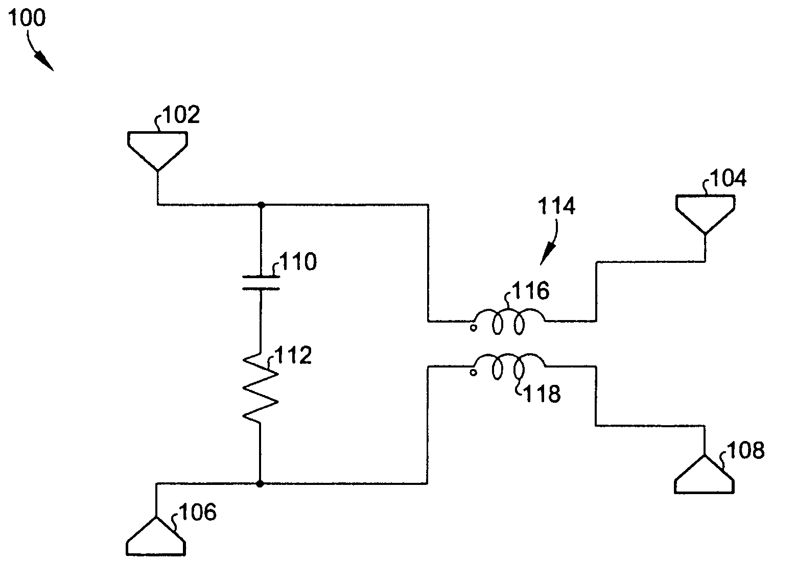
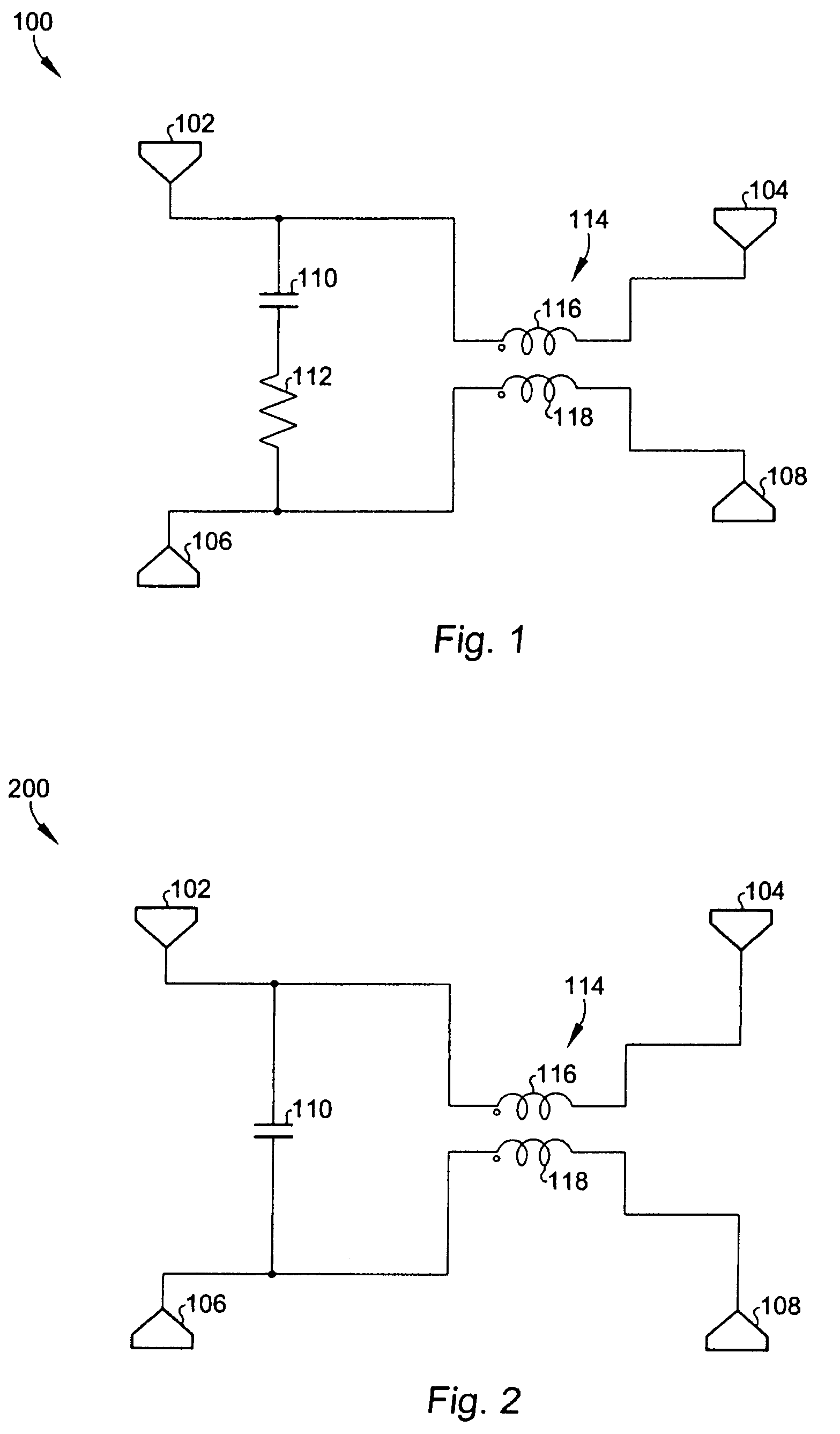
[0024]Referring now to FIG. 1, an RF coupler circuit 100 includes an input port 102, a coupling port 106, a load port 104, a ballast resistor port 108, a compensation circuit 110, 112 coupled between the input port and the coupling port, and a coupled inductor 114 having a first terminal coupled to the input port 102, a second terminal coupled to the coupling port 106, a third terminal coupled to the load port 104, and a fourth terminal coupled to the ballast resistor port 108. The coupled inductor 114 includes first and second inductors 116 and 118.

[0025]In a typical example optimized for wideband (0.8-6 GHz) operation, the inductance of the first and second inductors 116 and 118 is 0.6 nH. The series resistance for the first and second inductors is 1.2 ohms and the coupling coefficient between inductors 116 and 118 is about 0.7. The compensation circuit for coupler 100 includes a resistor 112 in series with a capacitor 110. The resistance of resistor 112 is 21.4 ohms. The capacita...


PUM


Abstract

Very small size true directional couplers have a coupling coefficient that is independent on load VSWR. The coupler uses coupled inductors with a compensation circuit including a resistor and a capacitor, or just a capacitor. Wideband operation is suitable for many portable applications such as power detection and control for GSM, DCS-PCS, CDMA / WCDMA, Bluetooth, and WLAN systems.

Description

BACKGROUND OF THE INVENTION[0001]The present invention relates to directional couplers used in RF applications.[0002]Directional couplers are used in many different RF applications such as power detection and control, test and measurement, mobile phones, and many others.[0003]Numerous types of couplers are known in the art. Micro-strip, strip-line, Lange-couplers and other directional couplers require a large size to obtain a reasonable coupling coefficient and low insertion loss over a wide frequency range. Consequently, these type of couplers increase total size and cost of, for example, mobile devices. L-C couplers used in current power detection applications (GSM, CDMA, WLAN, Bluetooth, etc.) are not “true” directional couplers and the coupling coefficient depends on a standing wave at the output (load VSWR dependent) resulting in incorrect power measurement and control. On-die implementation of micro-strip and other types of directional couplers is limited by high-frequency app...

Claims


Application Information

Patent Timeline
Patent Type & Authority Patents(United States)
IPC IPC(8): H03K7/04
CPCG01R27/06H01P5/185H03H7/48H03H7/46
Inventor GORBACHOV, OLEKSANDR
Owner STMICROELECTRONICS LTD
Why Eureka
Try Eureka