
Real-time obstacle detection with a calibrated camera and known ego-motion

a real-time obstacle detection and camera technology, applied in the field of obstacles, can solve problems such as inability to detect obstacles

Active Publication Date: 2008-11-04
KONINKLJIJKE PHILIPS NV
View PDF3 Cites 17 Cited by
  • Summary
  • Abstract
  • Description
  • Claims
  • Application Information

AI Technical Summary

Benefits of technology

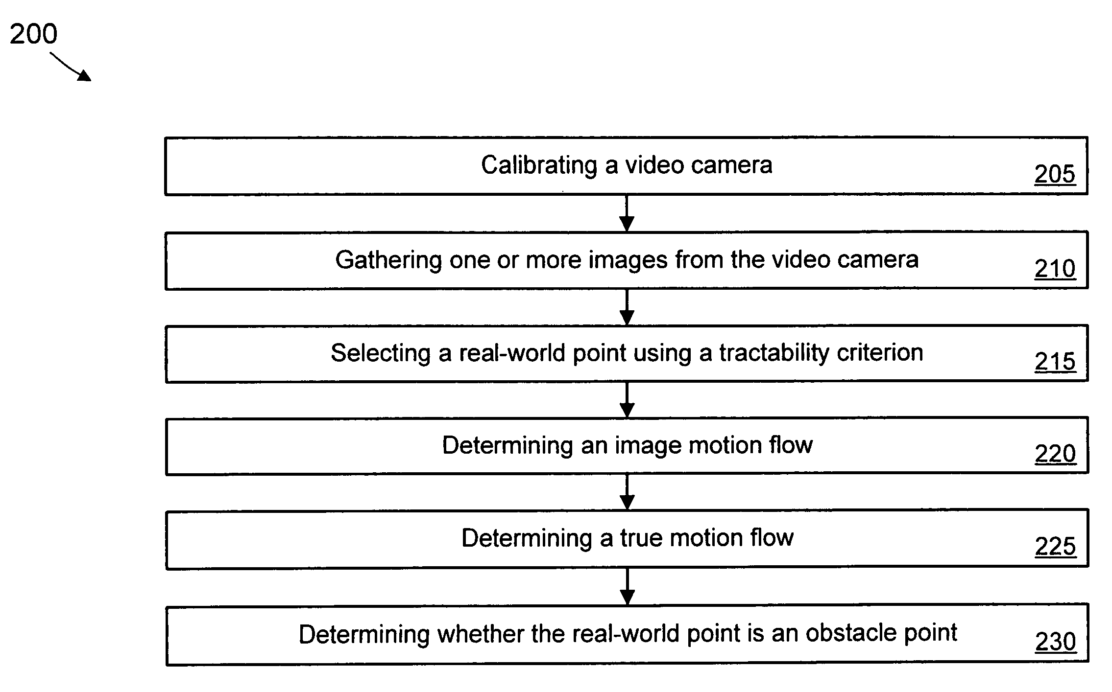
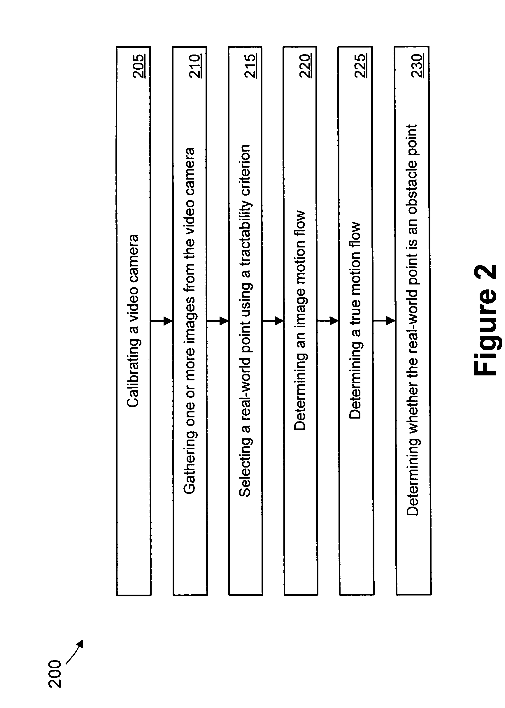
The present invention provides a method, system, and machine-readable medium for real-time obstacle detection from a vehicle moving relative to a road. The method involves calibrating an image capturing device, receiving images and information about the ego-motion of the device, selecting real-world points, applying a motion estimation method on the selected points, determining the true motion flow of the points, and identifying obstacle points based on the image motion flow and the true motion flow. The technical effects of the invention include improved obstacle detection and avoidance for safer driving.

Problems solved by technology

Problems with this method include its strong assumption that the obstacle must be a vehicle and its dependency on correct road and / or lane detection.
This method requires more than one camera, and it cannot detect obstacles with small heights moving on the road.

Method used


Image

  • Real-time obstacle detection with a calibrated camera and known ego-motion
  • Real-time obstacle detection with a calibrated camera and known ego-motion
  • Real-time obstacle detection with a calibrated camera and known ego-motion

Examples


Embodiment Construction

[0021]Illustrative embodiments of the invention are described below. In the interest of clarity, not all features of an actual implementation are described in this specification. It will of course be appreciated that in the development of any such actual embodiment, numerous implementation-specific decisions must be made to achieve the developers' specific goals, such as compliance with system-related and business-related constraints, which will vary from one implementation to another. Moreover, it will be appreciated that such a development effort might be complex and time-consuming, but would nevertheless be a routine undertaking for those of ordinary skill in the art having the benefit of this disclosure.

[0022]While the invention is susceptible to various modifications and alternative forms, specific embodiments thereof have been shown by way of example in the drawings and are herein described in detail. It should be understood, however, that the description herein of specific em...


PUM


Abstract

A method and system of real-time obstacle detection from a moving vehicle is provided. The method and system use a calibrated image capturing device. The method and system use a motion estimation technique to pick points with reliable image motion flows, and performs very fast sparse matching between the image motion flows and true motion flows calculated from the ego-motion of the image capturing device. Any mismatch between the image motion flows and the true motion flows are verified over time to achieve robust obstacle detection.

Description

CROSS REFERENCE TO RELATED APPLICATIONS[0001]This application claims the benefit of U.S. Provisional Application Ser. No. 60 / 445,203, filed on Feb. 5, 2003, which is incorporated by reference herein in its entirety.BACKGROUND OF THE INVENTION[0002]1. Field of the Invention[0003]The present invention relates to the field of obstacle detection, and, more particularly, to real-time obstacle detection with a calibrated camera and known ego-motion.[0004]2. Description of the Related Art[0005]Real-time obstacle detection in a moving vehicle is a key component for autonomous driving and computer vision-based driving assistance. Obstacle detection in autonomous driving and driving assistance is often used to avoid collision. An obstacle is generally context dependent. That is, although an obstacle on the road is usually a vehicle, it can be something else, such as a large rock.[0006]In Serge Beucher et al., Road Monitoring and Obstacle Detection System by Image Analysis and Mathematical Mor...

Claims


Application Information

Patent Timeline
Patent Type & Authority Patents(United States)
IPC IPC(8): H04N7/18G06K9/32G06T7/00
CPCG06K9/3241G06T7/004G06K2209/23G06T7/70G06V10/255G06V2201/08G01S2013/9323G01S2013/9324G01S13/867G01S15/86G01S17/86G01S17/931G01S15/931
Inventor COMANICIU, DORINXIE, BINGLONG
Owner KONINKLJIJKE PHILIPS NV
Learn More