
Adapter coupling device

a technology of coupling device and adapter, which is applied in the direction of chucks, mechanical devices, manufacturing tools, etc., can solve the problems of patents having the same disadvantage as the above described prior arts, inconvenient use, and inability to adapt to other types of screwdrivers

Inactive Publication Date: 2008-11-11
HUANG DANIEL
View PDF7 Cites 60 Cited by
  • Summary
  • Abstract
  • Description
  • Claims
  • Application Information

AI Technical Summary

Benefits of technology

"The present invention is an adapter coupling device that allows a user to insert a screwdriver into an adapter with one hand without sliding the outer sleeve up or downward. The device uses the pressing wall of the outer sleeve to secure the screwdriver inside the adapter. The device also provides a checking means to check the plane surface or the rhombic line of the hexagon screwdriver. Additionally, the device includes a W-shaped ring larger than 180° circumference to check the screwdriver in the adapter. The device ensures that the screwdriver is securely fixed inside the adapter and prevents it from breaking off during use. The device is easy to use and provides a secure and safe way to handle screwdriving operations."

Problems solved by technology

It is inconvenient because it always need other person helping to finish this job.
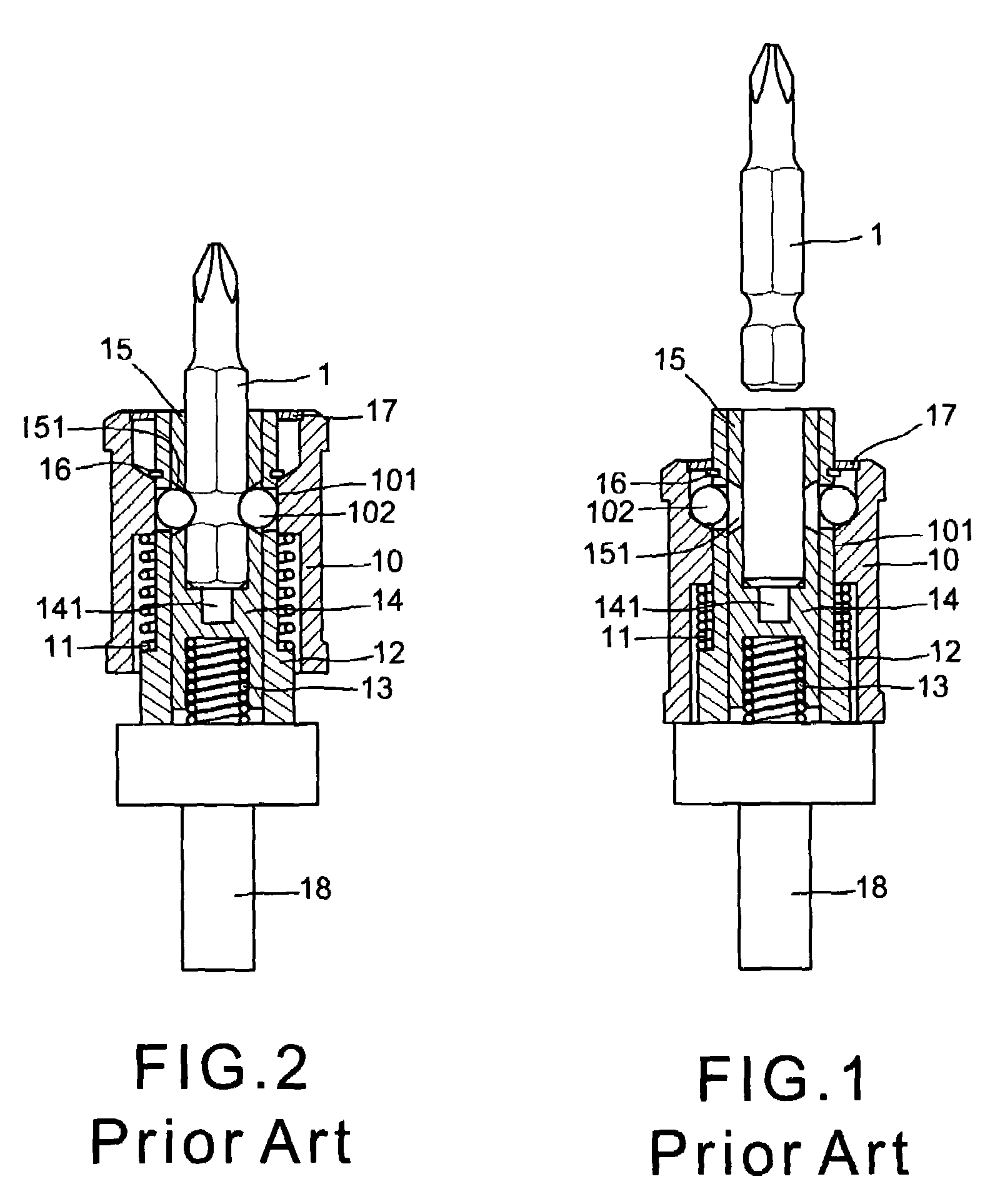
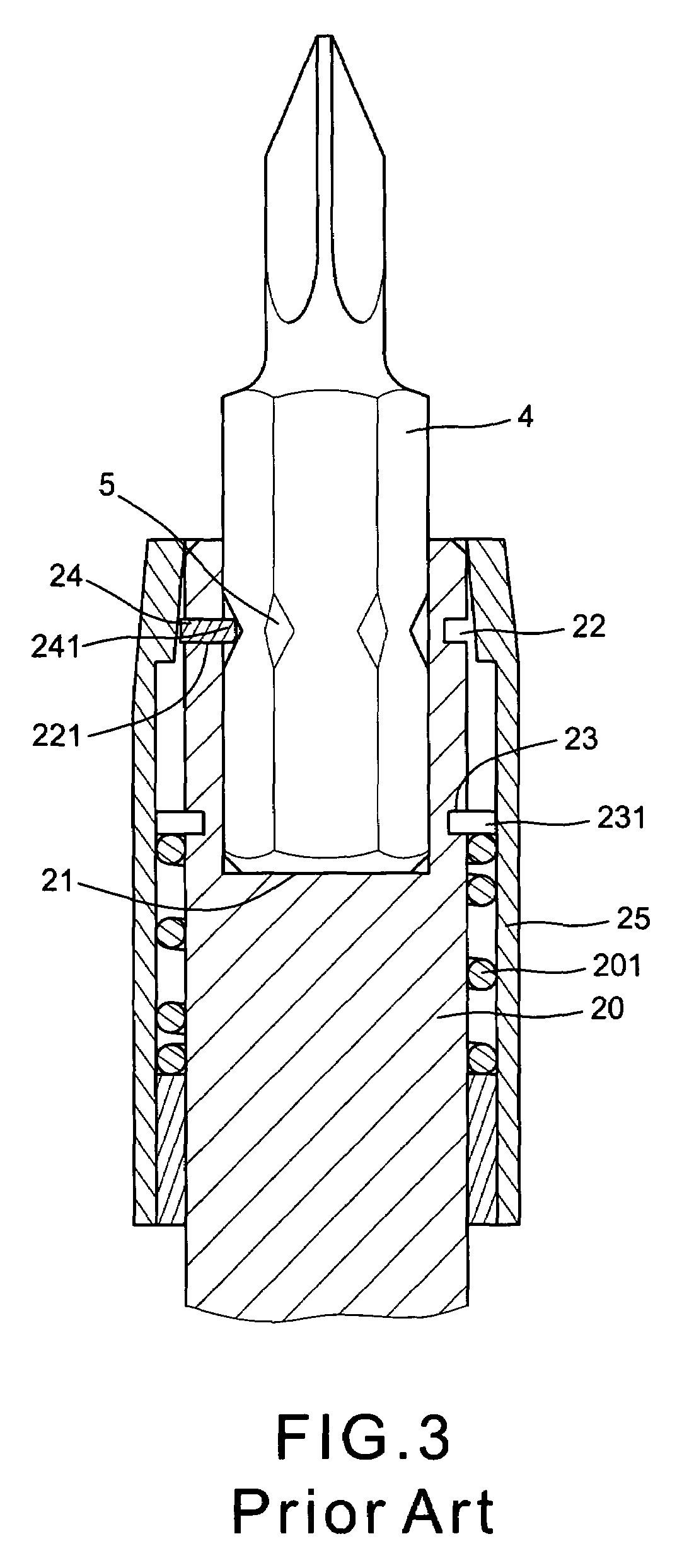
However, the user has to move the outer sleeve 25 upward with one hand preceding to insert the screwdriver 4 into the adapter 20 with other hand that's very inconvenient, too.
This patent has the same disadvantage that the user has to help by other person to engage or disengage the screwdriver 6 with the positioning recess 31 that's also inconvenient.
This patent has a disadvantage that the screwdriver must have an annular groove or a notch in periphery, other type of the screwdrivers are unsuitable.
This patent has the same disadvantage as the above described prior arts.
All of them have same disadvantage of unable to insert the screwdrivers into the positioning recess with one hand and no the function of temporarily keeping the screwdriver stable so that if inadvertently touch or knock the outer sleeve will cause the breaking-off of the screwdriver.

Method used


Image

  • Adapter coupling device
  • Adapter coupling device
  • Adapter coupling device

Examples


Embodiment Construction

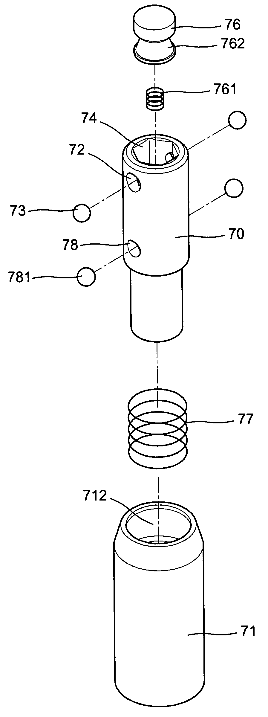
[0044]With reference to the drawings and initiated from FIGS. 12 to 16, the adapter coupling device of the preferred embodiment of the present invention comprises a cylindrical adapter 70 and an outer sleeve 71 wrapped on the adapter 70. The adapter 70 has a polygonal recess 74 (generally a tetragon or hexagon) in upper portion for inserting a screwdriver 4, a cylindrical recess 75 under the polygonal recess 74 communicating with each other, a pair of radial through holes 72 symmetrically formed in opposing upper peripheries for receiving a pair of steel balls 73 therein, a pair of radial through holes 78 symmetrically formed in the opposing peripheries of the cylindrical recess 75 for receiving a pair of another steel balls 781, a spring 761 disposed in the bottom of the cylindrical recess 75 for biasing a cylindrical positioning block 76, the lower portion of which is a conical outer periphery 762 including an upper slope 7621 and a lower slope 7622, a lower cylindrical groove 765...


PUM


Abstract

An adapter coupling device includes an adapter wrapped byan outer sleeve and biased by a large spring. The adapter has a polygonal recess in the upper portion, a circular recess under the polygonal recess for receiving a positioning block which is biased by a small spring, two pairs of the first and second radial through hole in upper and lower peripheries for engaging with two pairs of steel balls. The outer sleeve has an introrse upper portion which has an asymptotic inner wall, an annular groove in a middle inner wall and an annular flange on lower end, a screwdriver inserted into the polygonal recess of the adapter has a hexagon shank, a rhombic notch in each of the corners of the shank, when inserting the screwdriver into the adapter, the asymptotic wall of the sleeve is functioned to press the steel balls in the first radial through holes engaging within the rhombic notches of the shank so that the screwdriver is checked.

Description

BACKGROUND OF THE INVENTION[0001]The present invention relates to hand tools and more particularly to an adapter coupling device into which a screwdriver is positioned by using one hand and without pulling an outer sleeve for the outer sleeve is automatically moving backward simultaneously with the inserting action of the screwdriver and utilizing the asymptotic line or arc surface principles to force a retaining means (a ball, a cylinder or a W-shaped ring larger than 180° circumference) gripping the screwdriver inside the adapter. When removes the screwdriver from the adapter, pushes the outer sleeve upward and stops it at a positioning place. The screwdriver is although still stayed within the adapter. But the user can pick it up from the adapter freely without moving the outer sleeve downward so as to prevent an inadvertently touching on the outer sleeve that causes the screwdriver breaking-off the adapter.[0002]FIGS. 1 and 2 show “a pneumatic jaw structural improvement” which i...

Claims


Application Information

Patent Timeline
Patent Type & Authority Patents(United States)
IPC IPC(8): B25B23/00B23B31/107
CPCB25B23/0035Y10T279/17752
Inventor HUANG, DANIEL
Owner HUANG DANIEL
Learn More