Milking device and a method of handling a milking device

a technology of a milking device and a handle, which is applied in the direction of milking devices, catheters, dairy products, etc., can solve the problems of clogging of the aperture, flies, dirt, dust, etc., and achieve the effect of efficient and convenient cleaning

Active Publication Date: 2008-11-11
DELAVAL HLDG AB
View PDF29 Cites 7 Cited by
  • Summary
  • Abstract
  • Description
  • Claims
  • Application Information

AI Technical Summary

Benefits of technology

[0009]The object of the present invention is to overcome the problems mentioned above and to provide a secure and reliable gas supply to the milk-transporting member of a milking device. A further object is to provide an efficient and convenient cleaning of the gas supplying means.
[0011]By such an arrangement, a gas such as air may be supplied in a uniform flow during the milking state, i.e. during the milking of the animal, through the gas conduit forming a substantially closed passage for the gas from the gas inlet member to the milk-transporting member. Such a gas supply ensures and enhances the transport of milk from the teat to the milk-collecting member. Moreover, by means of the relatively low pressure, the cleaning fluid may be sucked through the gas conduit in an efficient and convenient manner during the cleaning state, so that said gas supply to the milk-transporting member during the milking state may be secured. Dirt and other particles, milk residuals, micro-organisms, etc. may thus be efficiently removed from the gas conduit, especially in the proximity of the first end forming a gas outlet into the milk-transporting member. Furthermore, the cleaning of the gas conduit may take place together with the cleaning of the teatcup, the milk-transporting member and further parts of the milking device, for instance as a part of the regular cleaning operation. No external jetting or spraying of any fluids is necessary for cleaning the gas conduit. The supply of the cleaning fluid may be performed within a closed system of components. The cleaning fluid is supplied through the gas conduit during the cleaning state when no milking takes place. In such a way, it may be ensured that the gas outlet mentioned above is clean and fully opened when every milking operation is initiated, and that no cleaning fluid will reach the milk and the milk-collecting member. The cleaning may be controlled to be performed according to a predetermined scheme, for instance between substantially every milking, every second milking, etc.
[0013]According to a further embodiment of the present invention, the gas inlet member is provided at a distance from the first end and from the milk-transporting member. By arranging the gas inlet member at a significant distance from the milk-transporting member and the teatcup, the gas inlet member may easily be protected from dirt, dust, micro-organisms etc. present in the environment surrounding the teatcup. For instance, the gas inlet member may include a conduit extending to a position outside the milking stall building.

Problems solved by technology

However, such gas inlets have the drawback that they often become filled up with dirt, dust, milk residuals, flies, etc.
A problem of such a milking device is that the aperture may get clogged by milk flowing through the teatcup and the milk line.

Method used


Image

  • Milking device and a method of handling a milking device
  • Milking device and a method of handling a milking device
  • Milking device and a method of handling a milking device

Examples


Embodiment Construction

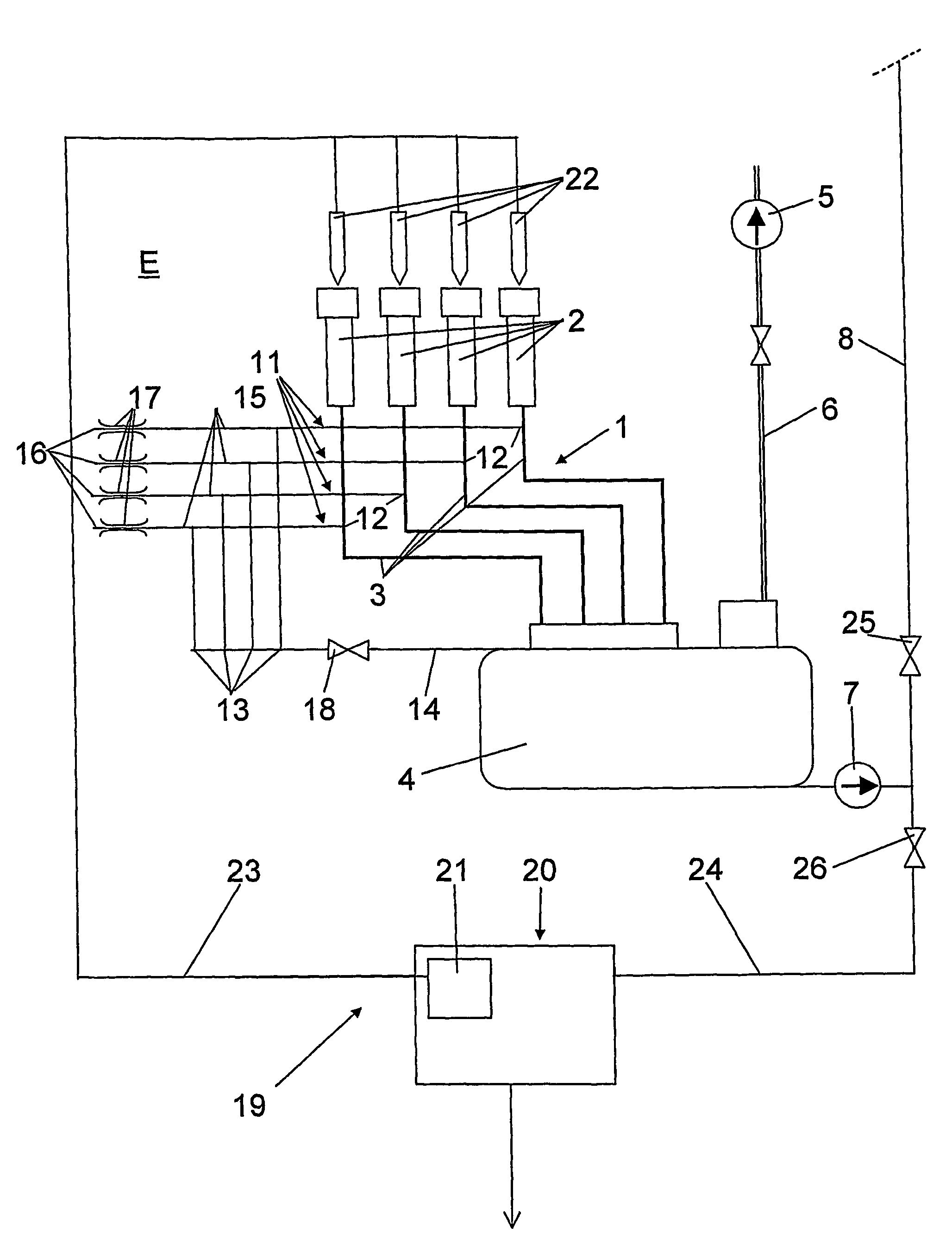
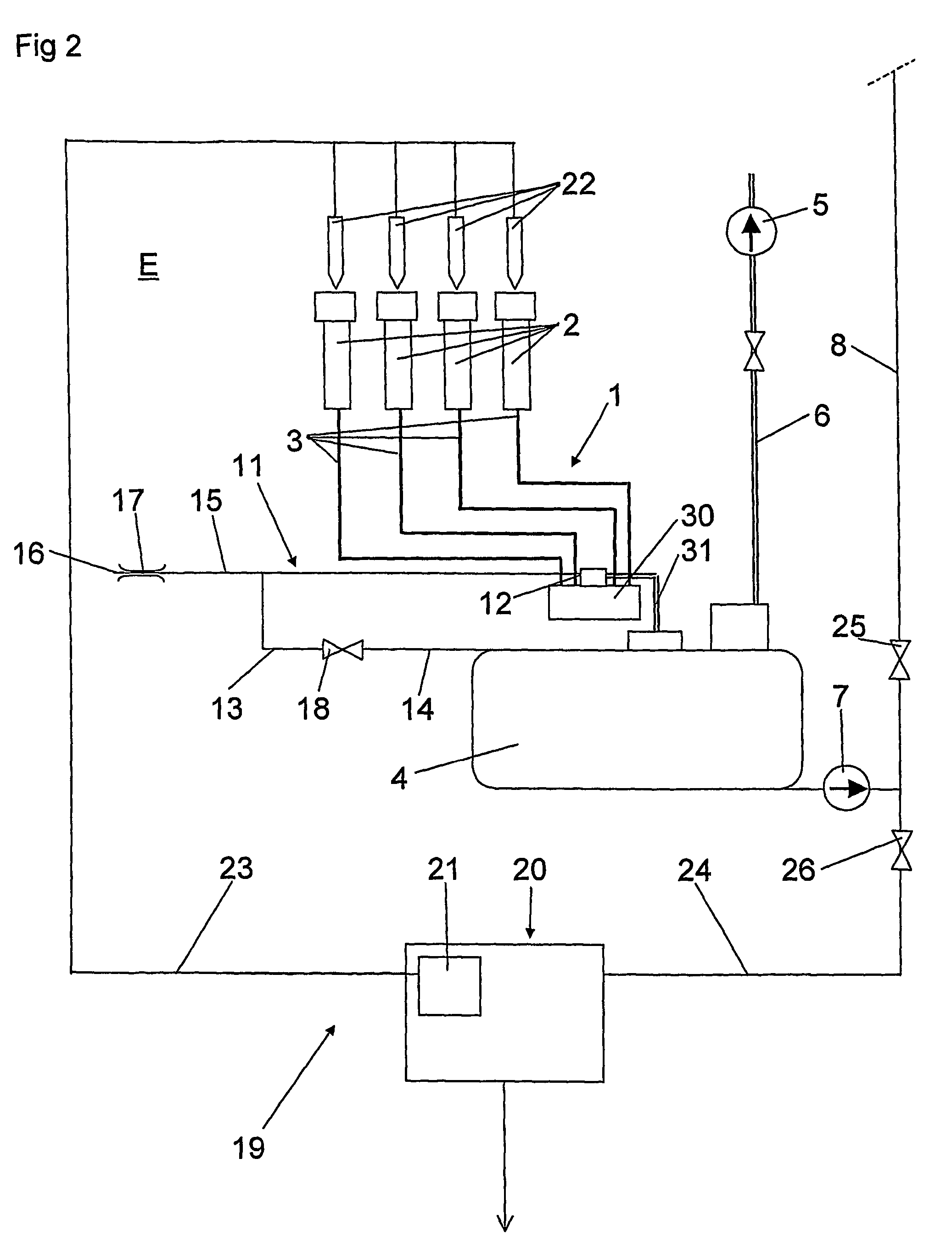
[0025]FIGS. 1 and 2 disclose a milking device for milking an animal such as cows. The invention is not limited to milking of cows but may also be applied to milking of other animals such as goats, cheep, horses, buffaloes etc. The milking device is operable in a milking state, during which the animal is milked, and a non-milking, cleaning state, during which the device is cleaned and not attached to an animal.

[0026]The milking device according to the first embodiment disclosed in FIG. 1 includes milk-transporting member 1, including four teatcups 2 and four milk hose 3, wherein each teatcup 2 is arranged at an end of a respective one of the milk hoses 3. Each teatcup 2 is adapted to be attached to a teat of the animal (not shown) to be milked. Each teatcup 2 may be of a conventional type with an inner space for receiving the teat, and a pulsation chamber for cyclically pulsating the wall defining the inner space. The milk-transporting member 1 is via the milk hoses 3 connected to a ...


PUM


Abstract

The invention refers to a milking device and a method of handling a milking device. The milking device includes a milk-transporting member (1) having at least one teatcup (2) and arranged to transport milk from a teat of an animal to a milk-collecting member (4) during a milking state. A low pressure is connected to the milk-transporting member (1) for sucking the milk from the teat to the milk collecting member. A gas conduit (11) permits the introduction of a gas into the milk-transporting member. The gas conduit has a first end (12), which is a gas inlet member (15). The gas conduit has a second end connectable to a relatively low pressure for permitting a flow of a cleaning fluid from the milk-transporting member through the gas conduit during a cleaning state.

Description

[0001]Applicant hereby incorporates by reference International Application PCT / SE2004 / 000971, filed 16 Jun. 2004, claiming priority from Swedish Application No. 0301934-6 filed 30 Jun. 2003 (also incorporated by reference herein).THE BACKGROUND OF THE INVENTION AND PRIOR ART[0002]The present invention refers to a milking device operable in a milking state and a cleaning state, the device including: a milk-transporting member, which includes at least one teatcup to be attached to a teat of an animal to be milked and is arranged to permit the transporting of milk from the teat to a milk-collecting member during the milking state, wherein the milk-transporting member is connectable to a relatively low pressure for achieving said transporting by sucking milk from the teat to the milk-collecting member via the milk-transporting member during the milking state; and a gas conduit for the introduction of a gas into the milk-transporting member during the milking state in order to enhance sa...

Claims


Application Information

Patent Timeline
Patent Type & Authority Patents(United States)
IPC IPC(8): A01J1/00A01J5/04
CPCA01J7/025A01J5/044A01J7/02
Inventor BOSMA, EPKEHOLMERTZ, NILS ERIKWASE, LARS
Owner DELAVAL HLDG AB
Why Eureka
Try Eureka