Although the LCD has been developed so that it can be used as picture display devices in various fields, the task to enhance the quality of images in such LCDs is made difficult by attempting to improve the above-mentioned features and advantages.
At this time, if the alignment of the liquid crystal layer is disordered, it is difficult to obtain a desired image.
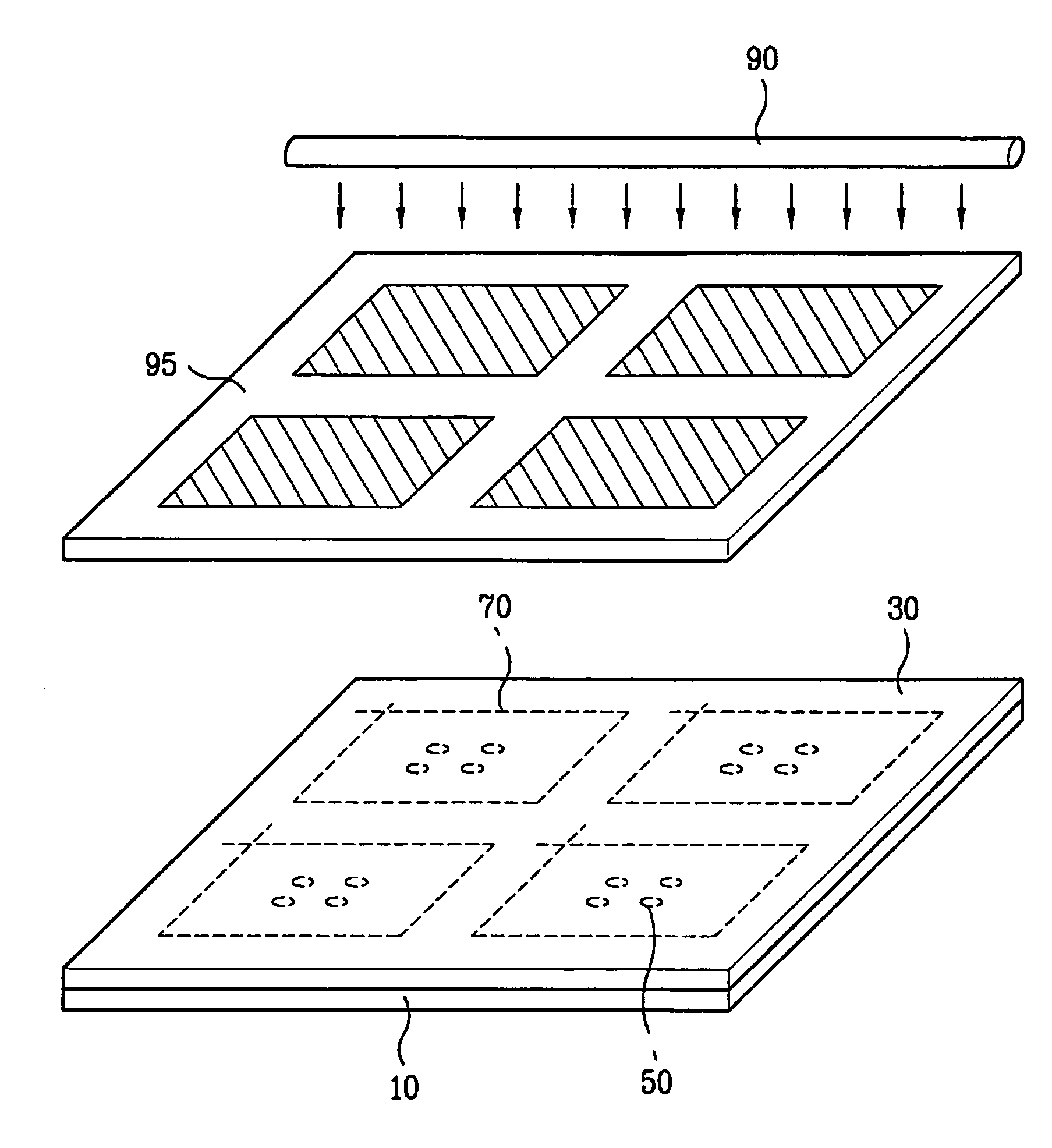
The orientation abnormality of liquid crystals is caused by an undesired increase in volume of the liquid crystal layer resulting from the temperature of the liquid crystal layer within the liquid crystal display panel being too high when manufacturing the liquid crystal display panel.
This causes the cell gap of the liquid crystal display panel to exceed the height afforded by the spacer.
Accordingly, liquid crystals move to the lower portion of the liquid crystal display panel as it sags, making the cell gap become non-uniform, and thereby deteriorating the quality of the liquid crystal display device.
That is, if any abnormality is detected in the image during an observation of the lower portion of the liquid crystal display panel, it is determined that there is orientation abnormality in the liquid crystal display panel.
That is, the orientation abnormality inspection is performed in a state in which the completed liquid crystal display panel is maintained at high temperatures.
However, such a related art inspecting apparatus for detecting orientation abnormality of the LCD panels has a problem in that, because the inspection apparatus is located a predetermined distance away from the heating chamber, the liquid crystal display panels are exposed to surrounding air and are cooled during conveyance to the inspection apparatus after being transferred from the cassette of the heating chamber, thereby making it impossible to perform a precise inspection.
In addition, the related art orientation abnormality inspecting apparatus has a problem in that, because the interior of the heating chamber is exposed to surrounding air while the liquid crystal display panels are transferred from the cassette of the heating chamber, the surrounding air is induced into the heating chamber, causing a non-uniform temperature of the heating chamber.
Furthermore, because the related art orientation abnormality inspecting apparatus requires expensive mechanisms, including a robot for conveying the liquid crystal display panels from the heating chamber to the inspector, manufacturing costs are invariably increased, and a lot of time is required to convey the liquid crystal display panels.
When the orientation of the liquid crystal layer is not uniform, it is difficult to obtain the desired image.
In this case, a problem occurs in that the alignment material is not uniformly coated on a center portion of the anilox roll 10222.
In this case, the alignment material is not uniformly coated on the abraded portion.
For this reason, a problem occurs in that a spot is generated on a predetermined portion of the substrate.
There are problems that arise in the related art rubbing process.
Meanwhile, the LCD device is being employed in electric devices such as TV sets as well as portable electric devices recently and accordingly, the size of the LCD device is greatly increasing (furthermore, the mother substrate for fabricating LCD panels is much greater in size) that results in an increase of the width and weight of the rubbing roll used to perform the alignment process for a large LCD device.
However, as the width and weight of the rubbing roll increases, it is difficult to uniformly maintain the pressure applied to the mother substrate, that results in the fabrication of a defective LCD device by defectively rubbing the alignment layer.
If the rubbing is not uniformly performed, an alignment degree of liquid crystal molecules is not spatially uniform, causing a defect that optical characteristics are different at a certain portion.
However, there is no means for keeping and storing the rubbing rolls, and the rubbing rolls are kept standing vertically, limiting the operation of rolls.
In addition, as the size of the mother substrate for fabricating a liquid crystal display panel increases, the corresponding rubbing roll lengthens, so there is a limitation on keeping rubbing rolls in a standing state in a clean room having a limited amount of space.
Furthermore, since the rubbing rolls are kept in a fixed state, the eccentricity of the rubbing roll deviates and changes.
Moreover, since the rubbing rolls are kept in an open, exposed state, the rubbing cloth is inevitably contaminated by external particles, thereby causing damage to the surface of the liquid crystal display panel.
However, disadvantageously, it takes a long time to inject liquid crystal into a panel through the injection hole 16.
Such injection of liquid crystal over a long period of time delays the fabrication process of the liquid crystal panel, and thus deteriorates fabrication efficiency.
Particularly, the vacuum injection method is inadequate for a large-sized liquid crystal panel because the time it takes to inject liquid crystal increases as liquid crystal panels become larger.
As a size of a substrate increases, it takes so much time in injecting liquid crystals by the vacuum injection method as to reduce manufacturing productivity.
In addition, because the sealant layer is hardened under the condition that the liquid crystal layer is formed between the lower and upper substrates, the liquid crystal drop method causes domain defects due to a scattering of the orientation of the liquid crystal layer from high temperatures during hardening the sealant layer.
However, in the liquid drop method, since the sealant layer is hardened after the liquid crystal layer is formed between the lower and upper substrates, the liquid crystal layer is exposed to high temperatures generated during hardening the sealant layer, and thus the orientation of the liquid crystal layer is scattered.
However, in the liquid crystal dropping method it is difficult to calculating the proper quantity of liquid crystals.
It is substantially difficult to calculate a precise quantity of liquid crystals due to various factors.
If the liquid crystal quantity calculated is too small, a filling-failure area of liquid crystals is generated within a liquid crystal display panel.
If the liquid crystal quantity calculated too large, an over-filling area is generated within a liquid crystal display panel, lowering the quality of the display.
Once the insufficient or excessive filling of liquid crystals takes place, there is no way in the related art to correct the insufficient or excessive filling of liquid crystals.
If the filling error is serious, the corresponding panel must be discarded, which is not economical.
If applying the screen printing method, the screen may come into contact with a substrate, whereby it may damage an alignment layer of the substrate.
First, because the sealant 10715 has a particular viscosity, the sealant 10715 may coagulate in the end of the nozzle 10720 of the dispenser. Thereafter, when the sealant material is supplied to the starting point (s) of the substrate 1071 through the nozzle 10730, the coagulated sealant is discharged to the starting point (s) of the substrate 1071. In addition, because the dispenser moves along the arrow direction from the starting point (s) of the substrate 1071, and then turns back to the starting point (s) of the substrate 1071, the coagulated sealant 10715 may be excessively dispensed to the starting point (s) of the substrate 1071. In this case, when bonding the two substrates to each other, the sealant 10715 spreads to the inside of the substrate 1071 in which the liquid crystal is formed. Thus, the liquid crystal dispensed on the substrate 1071 may be contaminated due to the spread of sealant.
Second, to prevent the sealant 10715 from being coagulated at the starting point (s), the dispenser may be stopped before the starting point (s). In this case, the sealant 10715 can be disconnected. That is, the liquid crystal flows to the outside through the disconnected portion of the sealant.
Thereafter, when another sealant material is supplied to the substrate 1081 through the nozzle 10820, the coagulated sealant is discharged to the starting point of the substrate 1081, thereby making it difficult to uniformly dispense sealant materials.
Because of this problem, it has been necessary to start dispensing the sealant in a dummy region away from the panel area.
The problem with these solutions is that they require the dispensing of sealant across the scribing or cutting path on the substrate.
Scribing or cutting through the hardened sealant can damage or wear out the scribing or cutting tool.
However, when an LCD device having a large area is being fabricated, a large substrate has to be transferred in a factory.
Since conveyors are not well suited for transferring the large substrate, the auto guide vehicle is mainly used to transfer the large substrate to a processing line.
However, the cassette of the related for an LCD device has the following problems.
However, when the pad 1094 is positioned within the LCD panel 1093 as illustrated in FIG. 16, if the substrate 10910 is pressed, the pad 10944 presses on an area of the LCD panel 1093 for displaying an image and a defect in the LCD device may result.
The above problem occurs primarily at the time of transferring attached LCD panels that have been received in the cassette 10940 to another processing line.
However, as illustrated in FIG. 17B, the above-mentioned conventional substrate bonding apparatus has a problem in that venting is non-uniformly carried out in the venting process, thereby causing the bonding quality of the substrates to be poor.
In this case, an air bubble may be introduced into the liquid crystal space, thereby causing the bonding quality of the substrates to be poor.
Thus, much time is required for the scribing process and the breaking process causing the problem of a reduction in productivity.
In particular, according to the cutting method of the liquid crystal display panel, since the mother substrates are struck with the breaking bar to make cracks along the prearranged cut lines formed on the mother substrates, a plurality of glass chips are generated, and if the striking is not performed inaccurately or if cracking is not incompletely made, the liquid crystal display panel would be damaged or torn off when it is extracted.
The significant amount of time used for the scribing process and the breaking process reduces productivity of the overall manufacturing process.
Further, if the striking is performed inaccurately or if crack propagation is incomplete, the liquid crystal display panel may be damaged or torn off when it is extracted.
However, several problems may occur when cutting the substrate using the cutting wheel and the pressing bar as follows.
Additionally dust may be generated when the dummy substrate is lowered.
Further, if a substrate is not cut into using the pressing bar, the uncut substrate is transferred to later processes resulting in stopping of the later process.
For example, a substrate defect may occur.
The varied depths of the scribing lines may result in portions of the substrate not being separated when applying the pressure to separate the unit LCD panels and portions of the substrate may be destroyed or taken away.
Secondly, foreign materials may be generated.
The generated foreign materials may cause defects in processes in processing lines in a factory.
However, the above described visual inspection apparatus for the LCD panel may generate problems as follows.
However, with a the large-sized LCD panel 1131, the corresponding large size of the polarizer 11330 makes it physically difficult or impossible for the operator to manually insert the jig pins 11326 into the holes 11327 of the jig 11332.

