
Dynamic random access memories and method for testing performance of the same

a random access memory and dynamic technology, applied in the direction of information storage, static storage, digital storage, etc., can solve the problems of data retention time being shorted, retention failure, and extremely low frequency of vrt failure occurren

Inactive Publication Date: 2008-11-11
LONGITUDE LICENSING LTD
View PDF4 Cites 9 Cited by
  • Summary
  • Abstract
  • Description
  • Claims
  • Application Information

AI Technical Summary

Benefits of technology

[0016]An object of the present invention is to establish a testing method for accurately screening off cells having the VRT failures, which can not be screened off by the pause / refresh test based on the conventional technology, not only within a short period of time but also without giving any damage to non-defective cells other than the VRT-defective memory cells.
[0017]The most important feature of the present invention consists in that the pause / refresh test is repeated optimized times under the same testing conditions to screen off VRT-defective memory cells. A frequency of VRT fluctuation tends to rise as a temperature goes higher, and therefore by repeatedly carrying out the pause / refresh test at a temperature higher than the ordinary operating temperature, the time required for testing can be shortened. Further during the pause / refresh test, by realizing, just before start of the pause / refresh test, a state in which a high reverse bias is applied to the PN junction in the storage node side of each memory cell or a state in which a forward bias is applied, or a state in which there is no electric field, the efficiency in detecting VRT-defective memory cells can be improved.
[0019]With the present invention, it is possible to screen off cells having the VRT failures, which can not be screened off by the pause / refresh test based on the conventional technology not only within a short period of time but also without giving any damage to normal cells other than the VRT-defective memory cells.

Problems solved by technology

In a memory cell showing the VRT phenomenon, even if it is determined that the data retention time is sufficiently long because the good state is observed in the shipment test, the data retention time becomes shorted because of occurrence of the bad state after shipment, which may sometimes cause retention failure.
Although the VRT failure is a serious failure for a customer, a frequency of occurrence of the VRT failure is extremely low.

Method used


Image

  • Dynamic random access memories and method for testing performance of the same
  • Dynamic random access memories and method for testing performance of the same
  • Dynamic random access memories and method for testing performance of the same

Examples


first embodiment

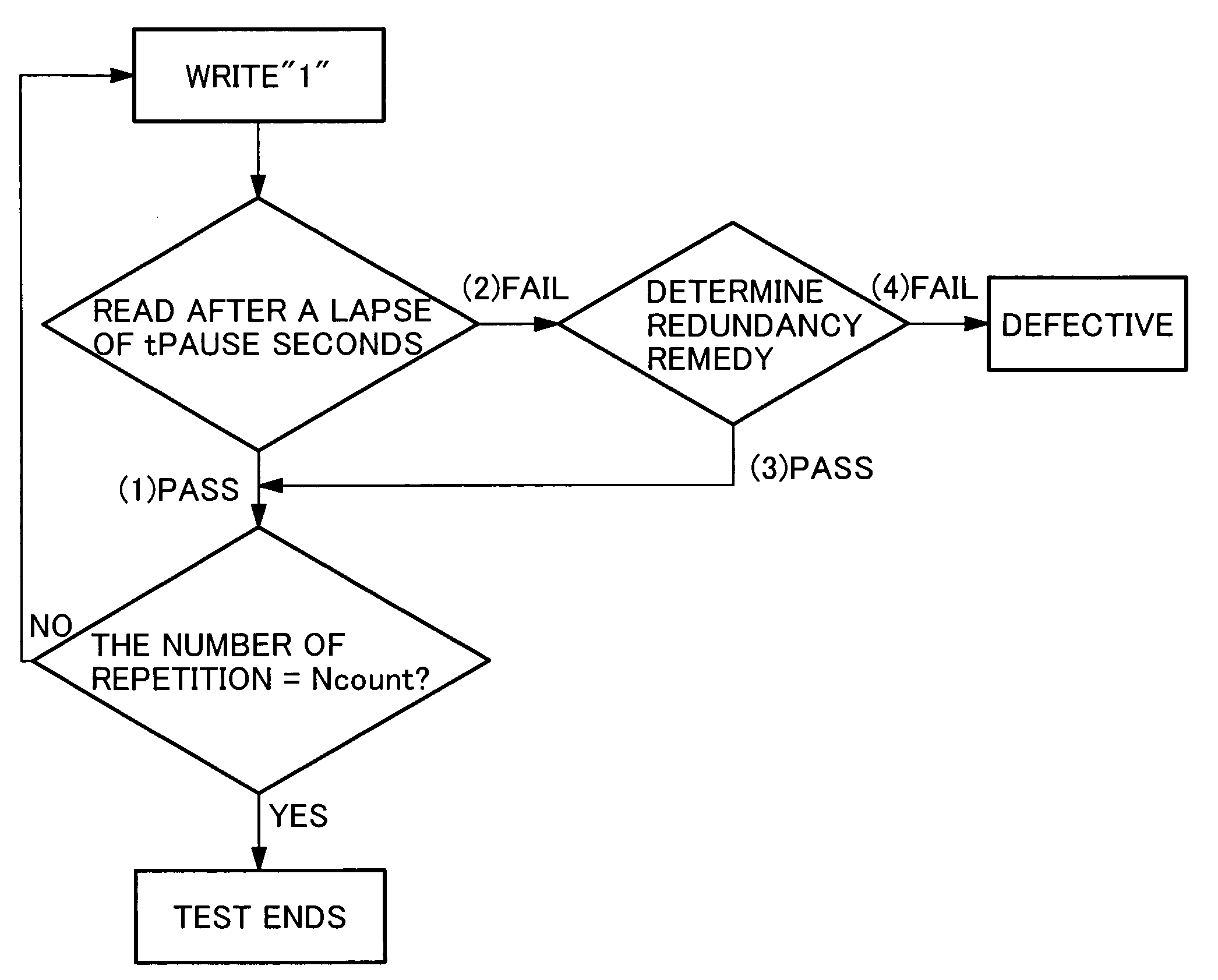
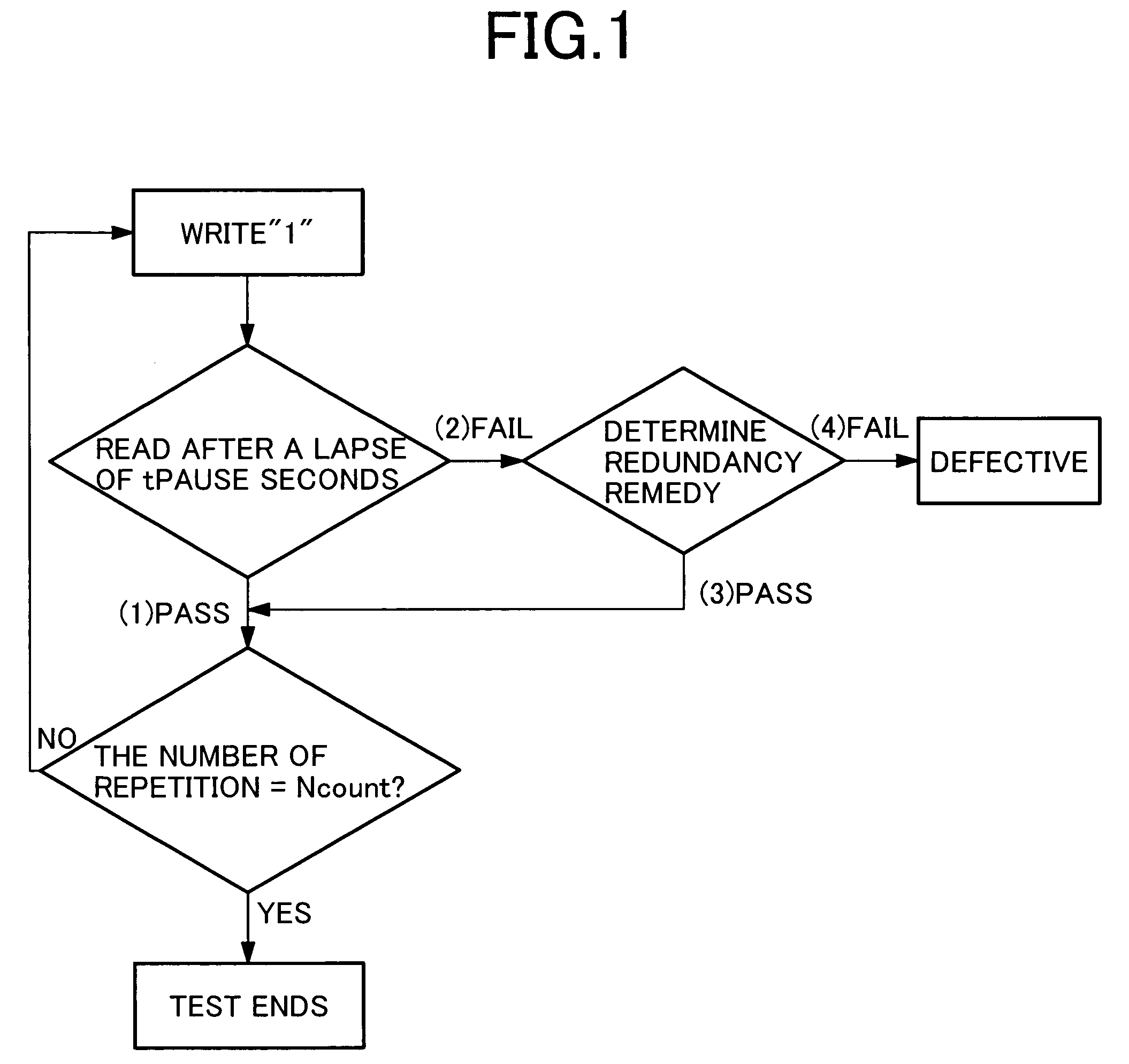
[0041]FIG. 1 illustrates a procedure of testing for a VRT failure screening according to a first embodiment of the present invention. This is a pause / refresh test based on a configuration starting by writing “1” to a memory cell followed by a pause for tPAUSE seconds and reading thereafter. For tPAUSE, an actual time of an interval of refresh time for operating a product or a slightly longer time than the same is selected. A cell that caused an error during the reading is regarded as a fail cell and a redundancy remedy is attempted (FIG. 1, (2)). The chip that caused an error here again is regarded as a defective product (FIG. 1, (4)). When all of the memory cells passes the test at the reading after the pause (FIG. 1, (1)), or when the redundancy remedy is valid (FIG. 1, (3)), the test described above is repeated for a specified number of repetition (Ncont). The pause of tPAUSE seconds described above may not be equal for each time of repetition.

[0042]When a chip under test include...

second embodiment

[0049]FIG. 7 shows a test procedure of testing for a VRT failure screening according to a second embodiment, and FIGS. 8 to 12 detail the bias conditions for testing. The feature of the present embodiment (FIG. 7) is to produce a state in which a high bias in the reverse direction is applied to the PN junction on the storage node side of the memory cell (FIG. 9) or a state in which an electric field is not present (FIG. 11) before each testing for the repeated pause / refresh test shown in FIG. 1. As described below, with the present embodiment, the VRT failures can be screened in a shorter time and more reliably than the first embodiment.

[0050]In order to reduce the time for screening the VRT failures, it is necessary to accelerate elicitation of the VRT failures, namely to increase the occurrence rate of the bad state per unit of time.

[0051]As a result of investigation for the occurrence rate of the bad state using some memory cells having the VRT failures as samples, the occurrence...

third embodiment

[0064]FIG. 13 shows a test procedure of testing for a VRT failure screening according to a third embodiment, and FIGS. 14 and 15 detail the bias conditions for testing. The feature of the present embodiment (FIG. 13) is that the step of voltage application in the electric field-free state in the repeated pause / refresh test described in the second embodiment is replaced by a step of bias application in the forward direction (FIG. 14).

[0065]It was stated in the second embodiment that the bad state more easily appears in some of the memory cells having the VRT failures when the bias (in the reverse direction) lower than writing “1” is applied to the PN junction on the storage node side. When the forward bias was applied to such a memory cell, it was found that the occurrence rate of the bad state increased as with the case of applying the low bias in the reverse direction.

[0066]FIG. 15 shows an example of the bias state in each terminal when the forward bias is applied immediately befo...


PUM


Abstract

The present invention enables screening of the so-called variable retention time (VRT) failure, namely a retention failure occurring in a DRAM due to fluctuation of a data retention time like a random telegraph noise. A pause / refresh test for checking a data retention function is repeated at all memory cells of a chip so that memory cells at which the retention failure due to random fluctuation of the data retention capability over time may occur is subjected to screening.

Description

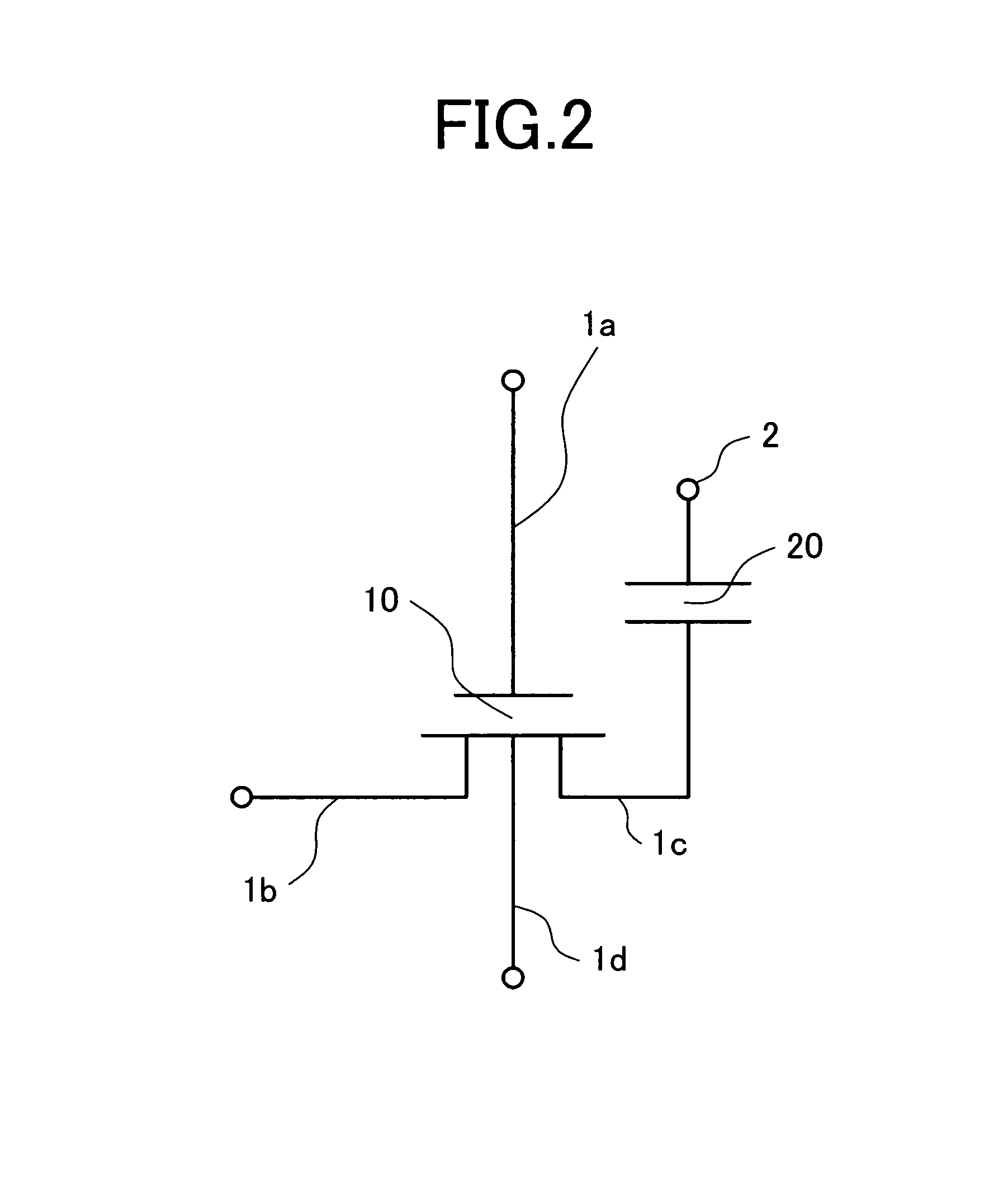
CLAIMS OF PRIORITY[0001]The present application claims priority from Japanese Application JP 2005-066657, filed on Mar. 10, 2005, the content of which is hereby incorporated by reference into this application.BACKGROUND OF THE INVENTION[0002]1. Field of the Invention[0003]The present invention relates to a dynamic random access memory and a method of testing performance of the same, and more specifically to a technique for accurately screening VRT failure in a dynamic random access memory within a short period of time.[0004]2. Description of the Related Arts[0005]An equivalent circuit of a memory cell in a dynamic random access memory (hereinafter referred to as DRAM) is shown in FIG. 2. In FIG. 2, reference numeral 10 denotes a switch transistor in a memory cell, namely a memory cell transistor, and a memory cell transistor 10 has four terminals of a word like 1a, a bit line 1b, a storage node 1c, and a substrate terminal 1d, and an accumulator / condenser 20. Furthermore the accumul...

Claims


Application Information

Patent Timeline
Patent Type & Authority Patents(United States)
IPC IPC(8): G11C11/34
CPCG11C29/50016G11C29/50G11C11/401G11C29/08
Inventor MORI, YUKIYAMADA, RENICHITSUKADA, SHUICHIOYU, KIYONORI
Owner LONGITUDE LICENSING LTD
Learn More