Variable focusing parabolic reflective lighting system

a parabolic reflective and variable technology, applied in the direction of lighting and heating equipment, point-like light sources, instruments, etc., can solve the problems of not being rugged enough for everyday motion picture and tv set work, unable to adjust the focal length of the light achieved by the type of reflector, and being heavy and functional

Inactive Publication Date: 2008-11-18
ECCE LUX
View PDF13 Cites 18 Cited by
  • Summary
  • Abstract
  • Description
  • Claims
  • Application Information

AI Technical Summary

Benefits of technology

[0008]An object of the present invention is to provide variable focussing parabolic reflective lighting systems for photography, which change their parabolic shape to provide a controllable and variable lighting effect.
[0009]The lighting system of the present invention includes a bright bulb installed in front of a reflective element comprising a plurality of curved leaves forming a generally parabolic shape. The leaves have some overlap and are pivotally attached near the base of the bulb, so that they can be collapsed inward or expand outward, changing the parabolic shape. As the shape changes, the light from the bulb reflects off of different portions of the parabola in different amounts and is bounced toward the subject in a controllable fashion. The changing shape of the parabola causes the light to follow different pathways as it bounces inside the reflector before reaching the subject. When narrowly closed, the back of the reflector reflects the majority of the light and produces a very intense, concentrated cone of light. When widely open, the light is reflected from the entire reflector and produces a very soft, diffuse, and scattered bounce light. Altering the parabolic shape from a wide open, almost flat shape, through a variety of in between shapes, to a narrow, steeply curved shape, alters the focal length of the parabola, and hence alters the intensity, coverage, quality and quantity of light reflected onto the photographic subject.

Problems solved by technology

Such systems, though lightweight and functional, offer extremely limited adjustability of the focus of light in shape and intensity.
Furthermore such umbrella systems are not rugged enough for everyday motion picture and TV set work, as they are unstable in windy conditions, cannot withstand very high temperatures, and are made of delicate fabrics prone to rips and snags.
This type of reflector has no adjustability as to the focal length of the light achieved.

Method used


Image

  • Variable focusing parabolic reflective lighting system
  • Variable focusing parabolic reflective lighting system
  • Variable focusing parabolic reflective lighting system

Examples


Embodiment Construction

[0022]The following table of reference numbers used herein are provided for convenience.

[0023]

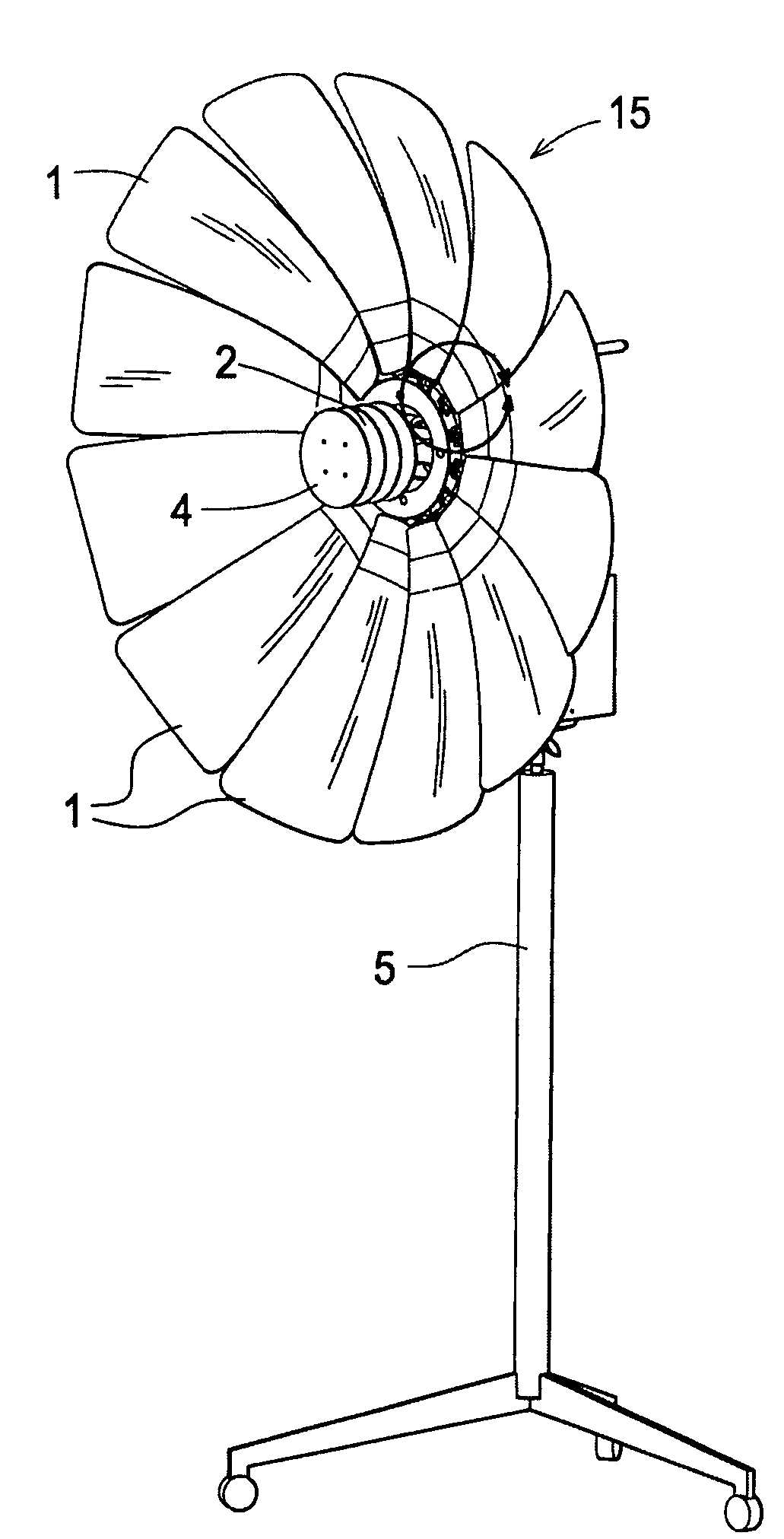
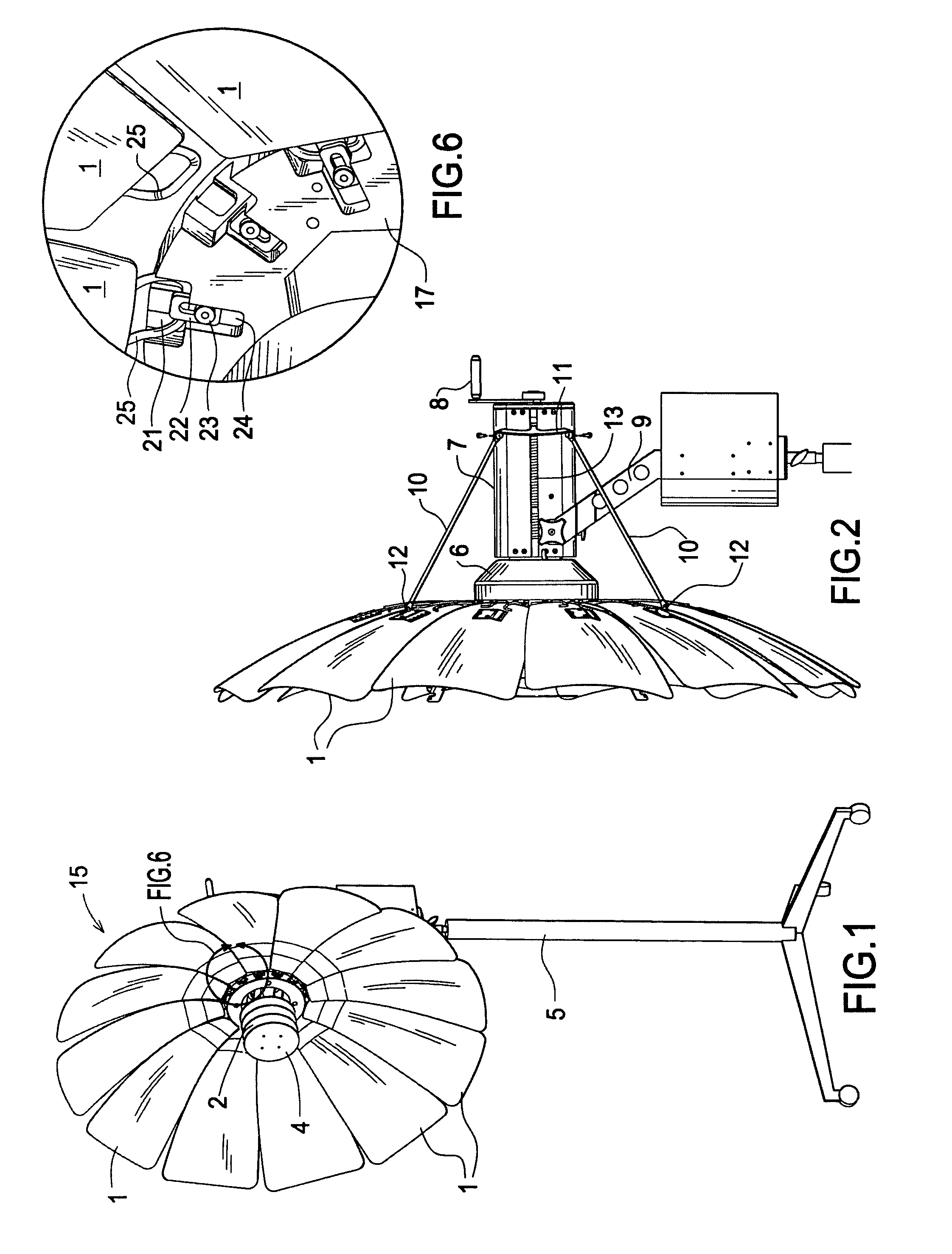
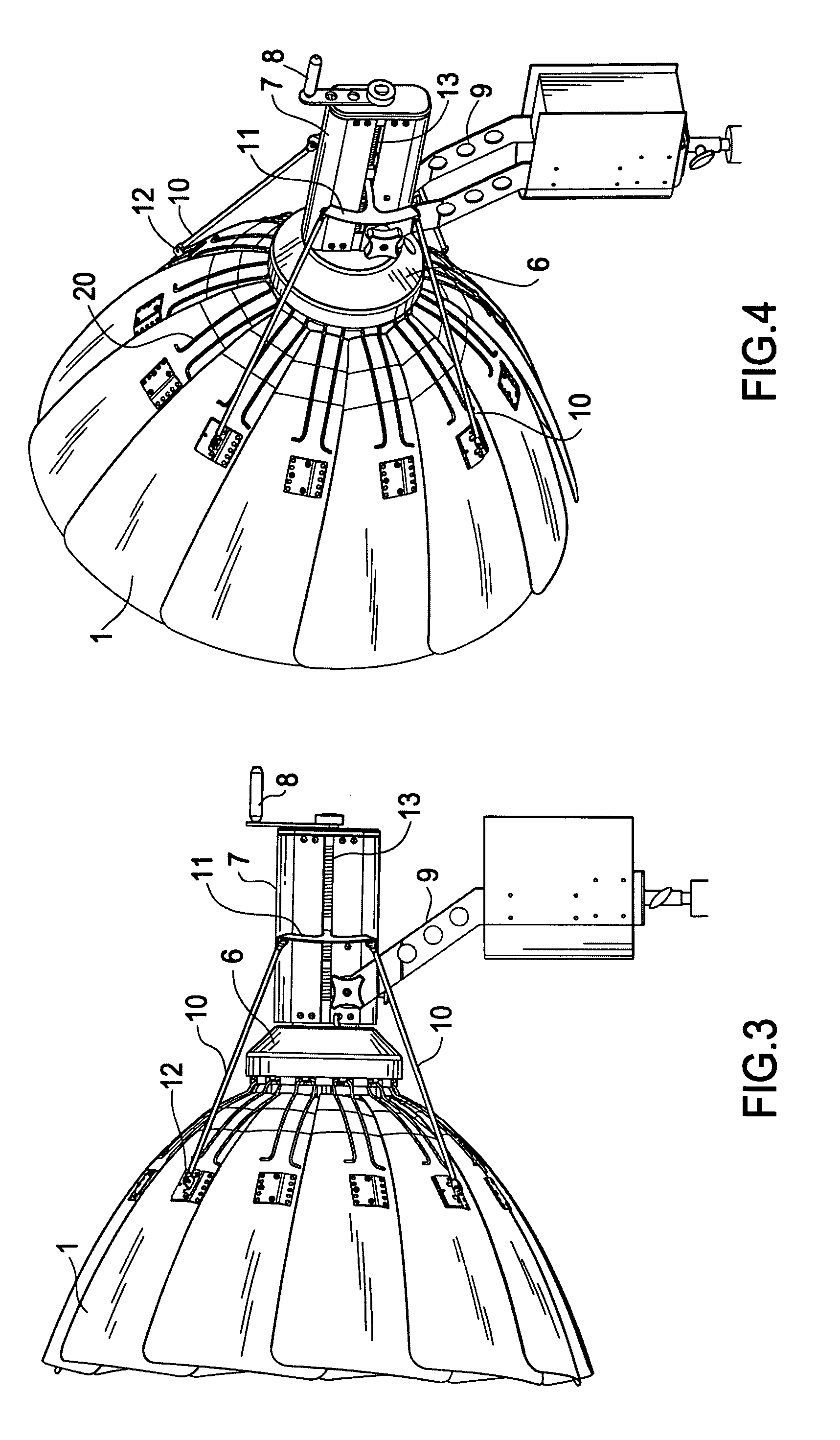
1leaves2baffle3lighting element4light shield5Reflector assembly stand6front portion of housing7back portion of housing8adjustment handle9mounting bracket10linkage rods11linkage rod connection element12linkage rod leaf connectors13lead screw14light source electronics15variable reflector assembly17leaf connection ring18lamp base20leaf support wire21wire loop support channel22wire retaining washer23tightening nut24washer retraction channel25wire loop

[0024]FIG. 1 is a front isometric view of a variable focus lighting system according to the present invention, including its optional stand 5. Stand 5 is conventional and not described in detail. It will generally include such features as height adjustment and means to rotate the reflector assembly 15 from side to side, in order to direct the light toward a photographic subject.

[0025]Reflector assembly 15 is the heart of the present invention and i...


PUM


Abstract

A lighting system includes a bright bulb installed in front of a variable reflector assembly comprising a plurality of leaves. The leaves have some overlap and are pivotally attached near the base of the bulb, so that they can be collapsed inward or expanded outward in tandem by a mechanism. A baffle and light shield enclose and protect the bulb, and result in controllable and variable indirect lighting from the bulb.

Description

BACKGROUND OF THE INVENTION[0001]This application claims the benefit of U.S. Provisional Patent Application No. 60 / 709,375, filed Aug. 18, 2005, and incorporates it by reference.FIELD OF THE INVENTION[0002]This invention relates to variable focusing parabolic reflective lighting systems for photography. In particular, this invention relates to variable focus lighting systems having leaves for forming a collapsible parabola shape.DESCRIPTION OF RELATED ART[0003]Reflectors are used to achieve lighting effects in photography, including still photography, motion picture filming, television filming, and the like. Designs for collapsible reflectors for bouncing light into reflectors and achieving a soft indirect effect date to 1909 with U.S. Patent No. 923,542 to Losy, in which an umbrella like structure containing ribs covered with fabric was used as a surface into which to bounce light. Similar designs have improved the construction of light source and umbrella units, such as in U.S. Pa...

Claims


Application Information

Patent Timeline
Patent Type & Authority Patents(United States)
IPC IPC(8): F21V1/00
CPCG03B15/02G03B2215/051
Inventor MAZZEI, MARCO
Owner ECCE LUX
Why Eureka
Try Eureka