Multi-piece turbine vane assembly

a turbine vane and multi-piece technology, applied in the direction of machines/engines, liquid fuel engines, lighting and heating apparatus, etc., can solve the problems of reduced engine efficiency, costly repair, and reduced manufacturing yield, so as to prevent the pre-tensioning of the airfoil segment

Inactive Publication Date: 2008-11-18
SIEMENS ENERGY INC
View PDF30 Cites 142 Cited by
  • Summary
  • Abstract
  • Description
  • Claims
  • Application Information

AI Technical Summary

Benefits of technology

[0005]The fastener can include opposing ends. At least one end of the fastener can include a shoulder with a shaft extending therefrom. The shaft can be threaded. The shoulder can engage one of the shrouds, and the shaft can extend through at least a portion of the shroud. Such an fastener system can substantially prevent pre-tensioning of the airfoil segment.

Problems solved by technology

However, experience has demonstrated that no single material is ideal for every portion of the vane and that vanes made of a single material can actually lead to a decrease in engine efficiency.
Such unitary vanes can result in lower manufacturing yields, costly repair, and expensive replacement inventories.
In addition, the relatively large size of the unitary vanes made the use of certain materials infeasible.

Method used


Image

  • Multi-piece turbine vane assembly
  • Multi-piece turbine vane assembly
  • Multi-piece turbine vane assembly

Examples


Embodiment Construction

[0031]Embodiments of the present invention provide a modular vane assembly. Embodiments of the invention will be explained in the context of various possible vane assemblies, but the detailed description is intended only as exemplary. Embodiments of the invention are shown in FIGS. 1-16, but the present invention is not limited to the illustrated structure or application.

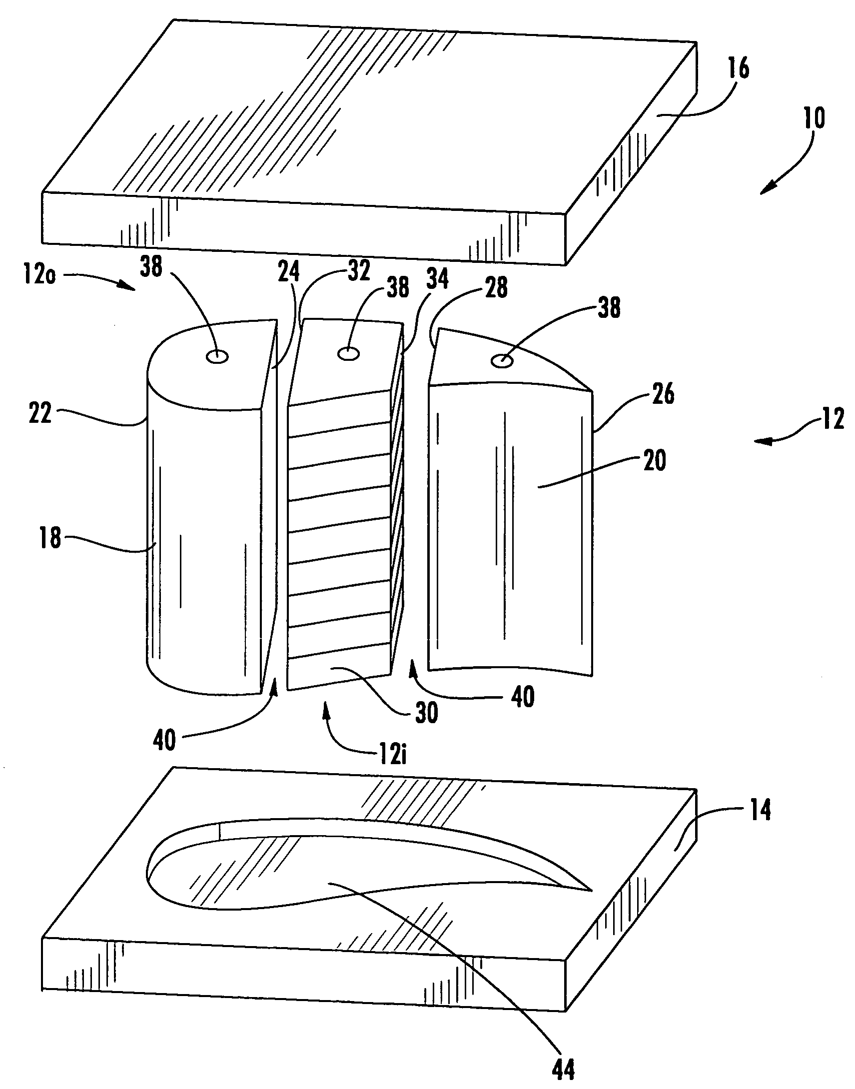
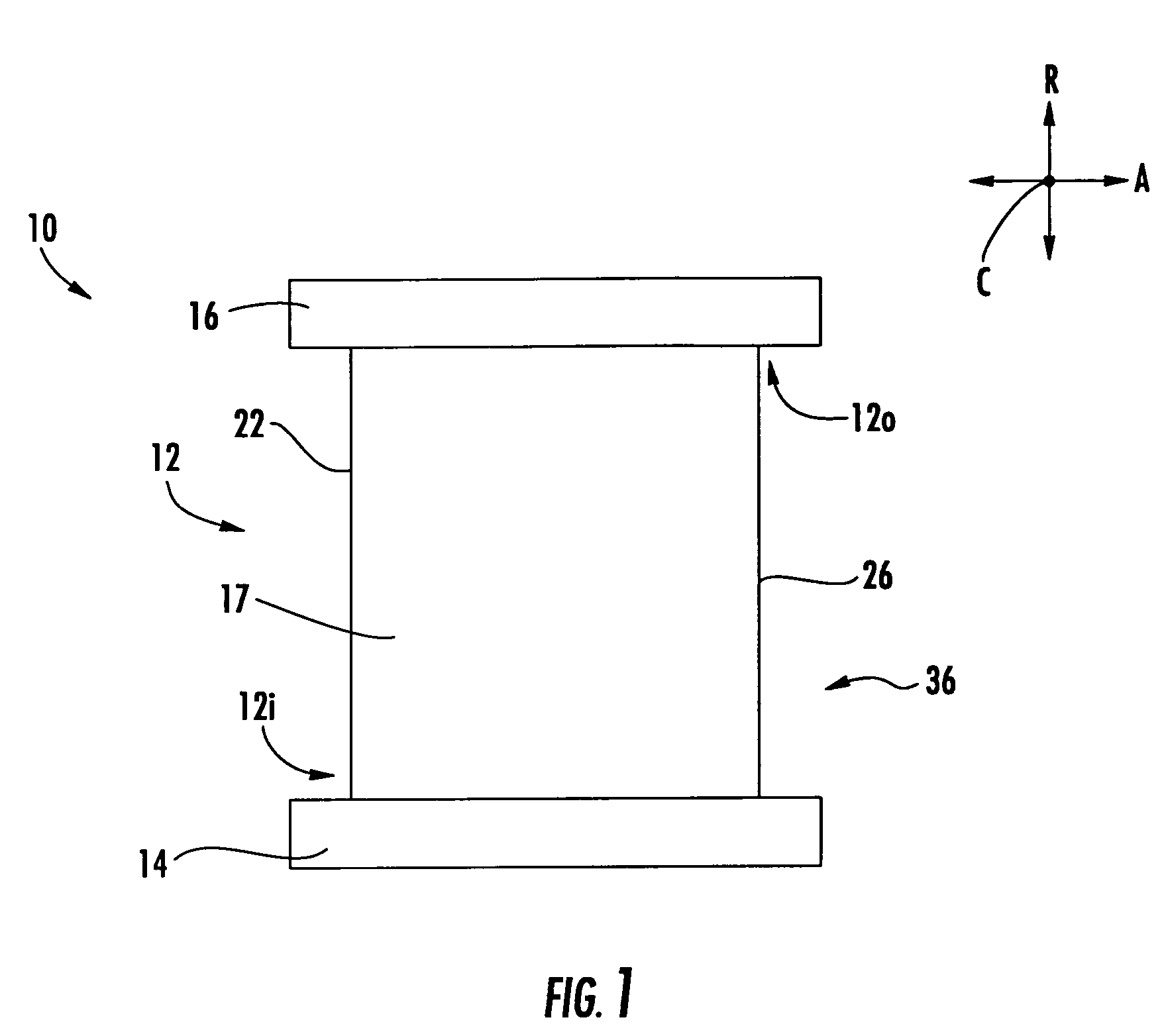
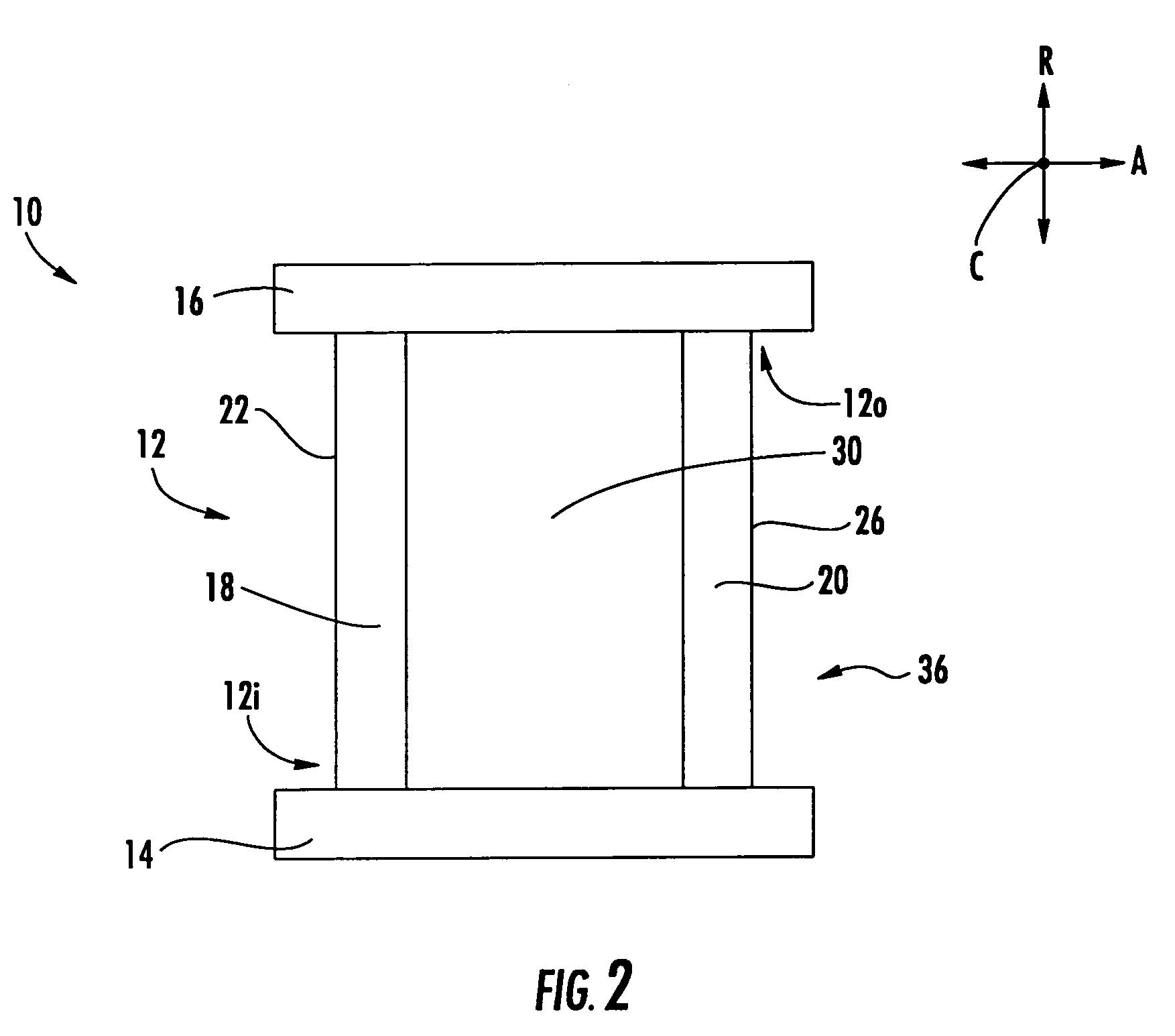
[0032]A vane assembly 10 according to aspects of the invention can have several separate sub-components. The vane assembly 10 can include at least an airfoil portion 12, an inner shroud 14 and an outer shroud 16. According to embodiments of the invention, at least one of the airfoil 12, inner shroud 14 or outer shroud 16 can be separately formed. In one embodiment, each of these components 12, 14, 16 can be separately formed and then subsequently assembled to form the vane assembly 10. In some instances, some of these components can be formed as a unitary construction. For example, the airfoil 12 can be unitary with...


PUM


Abstract

Aspects of the invention relate to a modular turbine vane assembly. The vane assembly includes an airfoil portion, an outer shroud and an inner shroud. The airfoil portion can be made of at least two segments. Preferably, the components are connected together so as to permit assembly and disassembly of the vane. Thus, in the event of damage to the vane, repair involves the replacement of only the damaged subcomponents as opposed to the entire vane. The modular design facilitates the use of various materials in the vane, including materials that are dissimilar. Thus, suitable materials can be selected to optimize component life, cooling air usage, aerodynamic performance, and cost. Because the vane is an assemblage of smaller sub-components as opposed to one unitary structure, the individual components of the vane can be more easily manufactured and more intricate features can be included.

Description

FIELD OF THE INVENTION[0001]The invention relates in general to turbine engines and, more specifically, to turbine vanes.BACKGROUND OF THE INVENTION[0002]During the operation of a turbine engine, turbine vanes, among other components, are subjected to a variety of loads. The vanes can be made of any of a number of materials, and each material can provide certain advantages in managing the operational loads imposed on the vane. Prior turbine vanes have been made of a single material. However, experience has demonstrated that no single material is ideal for every portion of the vane and that vanes made of a single material can actually lead to a decrease in engine efficiency. Prior vanes have also been formed with the airfoil portion and the shrouds as a unitary construction, such as by casting. Such unitary vanes can result in lower manufacturing yields, costly repair, and expensive replacement inventories. In addition, the relatively large size of the unitary vanes made the use of c...

Claims


Application Information

Patent Timeline
Patent Type & Authority Patents(United States)
IPC IPC(8): F01D9/04
CPCF01D5/14F01D5/147F01D5/28F01D9/041F05D2230/50
Inventor VANCE, STEVEN J.JAMES, ALLISTER W.
Owner SIEMENS ENERGY INC
Why Eureka
Try Eureka