Spine microsurgery techniques, training aids and implants

a technology of microsurgery and implants, applied in the field of human spinal implant systems and methods, can solve the problems of pain and disability of a large segment of the population, loss of stability, and loss of height of the intervertebral disc, and achieve the effect of enhancing safety and broad utility

Inactive Publication Date: 2008-11-18
BARRY RICHARD J
View PDF40 Cites 190 Cited by
  • Summary
  • Abstract
  • Description
  • Claims
  • Application Information

AI Technical Summary

Benefits of technology

[0019]The system and methods of the present invention provide a comprehensive, minimally invasive surgical solution to the biomechanical problems currently encountered by spine surgeons. The system includes a novel spine surgical training aid used in surgeon education, for ongoing use as a pre-operative reference to the critical three dimensional anatomy of the vertebrae, and as a simple method of teaching the fluoroscopy technician how to provide perfect reproducible views of each vertebrae during the procedure. The training aid has broad utility in enhancing the safety of all of the current minimally invasive spine surgical procedures.
[0032]In addition, the outer surface may be roughened to create the interference fit the first and second vertebrae. For example, the roughened external surface may comprise tantalum beads or other materials which are biocompatible with ingrowth of bone into the outer surfaces of the implant. The roughened external surface may also be plasma sprayed with calcium hydroxyapatite crystals to enhance the immediate biologic fixation of the implant with the surrounding cancellous bone. In addition, the roughened external surface may have undulations, teeth or ridges. Ideally, the external surface of the implant is configured to interdigitate with the bone surrounding the joint surfaces providing an immediate mechanical interlock of the intervertebral facet articulations. Immediate mechanical immobilization of the highly cellular periarticular cancellous bone exposed by the drilling and implantation of the device is an important aspect of the implant system, which is beneficial in protecting the cellular healing response which produces the bone formation and osseous fusion through the implant and between the articular processes of the adjacent vertebrae to promote osseous fusion.
[0035]In some embodiments, the outer surface has an outer diameter sized to create the interference fit with the bone surrounding the kerf. The outer surface may also be roughened to create the interference fit. The roughened external surface may have one or more fenestrations, the fenestrations promoting growth of cancellous bone surrounding the ring. The fenestration may comprise circular holes or parallel columns running axially along the outer cylindrical surface. The fenestrations may also have raised edges at their perimeters, the raised edges forming an interference fit with the surrounding bone of the kerf. In addition, the outer surface may also have a tapered leading edge to facilitate installation of the ring.
[0042]In a preferred embodiment, the training device includes one or more of color coded regions correlating to an area of interest for a step in the procedure. Each simulated vertebrae is bored out along the locus of safe passages from the point of initial approach on the posterior-lateral portion of the vertebra which will be blindly transgressed during a fluoroscopically-guided cannulation of the pedicle in an approach to the center of the vertebral body. This ‘hollowing out’ of the safe instrument trajectory fields within the vertebrae provides a clear visualization of the anatomy which the surgeon and his / her fluoroscopic technician will see on the image monitor during the actual surgical procedure. The training apparatus may also comprise one or more color coded glass markers, such as erasable marking crayons, for reference to anatomical images on a radiographic display, the colors of the markers correlating to the colors of the coded regions of the spine structure. The color-coded, clear step-wise approach to the positioning of the fluoroscope, combined with the clear image of the geometry of the training aid creates a reproducible, safe approach to the complex spinal anatomy, surrounded on all sides by delicate structures.

Problems solved by technology

Chronic back problems cause pain and disability for a large segment of the population.
In many cases, the chronic back problems are caused by intervertebral disc degeneration and loss of stability of the intervertebral joint.
Over time, the process of aging produces progressive dehydration and loss of height of the intervertebral discs.
The shortening of the spinal articular segment produces increased mechanical wear of the facet joints.
With the increasing pressure across the facet joints, the articular cartilage on each surface of the joints undergoes abrasive thinning, producing pain.
Currently there exists no direct, efficient procedure to achieve consistent fusion or arthrodesis of the posterior-lateral facet joints of the lumbar spine.
The classic procedures for posterior-lateral fusion of the lumbar spine require long posterior midline incisions, are frequently associated with massive blood loss occurring during prolonged operations, produce widespread paraspinous muscle damage resulting from the extensive retraction forces necessary for visualization, and yield unacceptably high clinical failure rates.
The cost of failed spine surgery is enormous.
Persistent pain, lost productivity and the disappointingly low success rate of revision surgery underscore the need for more effective primary lumbar spine fusion surgery.
Translaminar facet screw fixation has not been widely adopted since it is much more technically demanding than other current fixation systems, requires multiple incisions, places the dura at risk and depends upon an intact lamina.

Method used


Image

  • Spine microsurgery techniques, training aids and implants
  • Spine microsurgery techniques, training aids and implants
  • Spine microsurgery techniques, training aids and implants

Examples


Embodiment Construction

[0076]Referring more specifically to the drawings, for illustrative purposes the present invention is embodied in the systems and methods generally shown in FIG. 1 through FIG. 27D. It will be appreciated that the systems may vary as to configuration and as to details of the parts, and that the method may vary as to the specific steps and sequence, without departing from the basic concepts as disclosed herein.

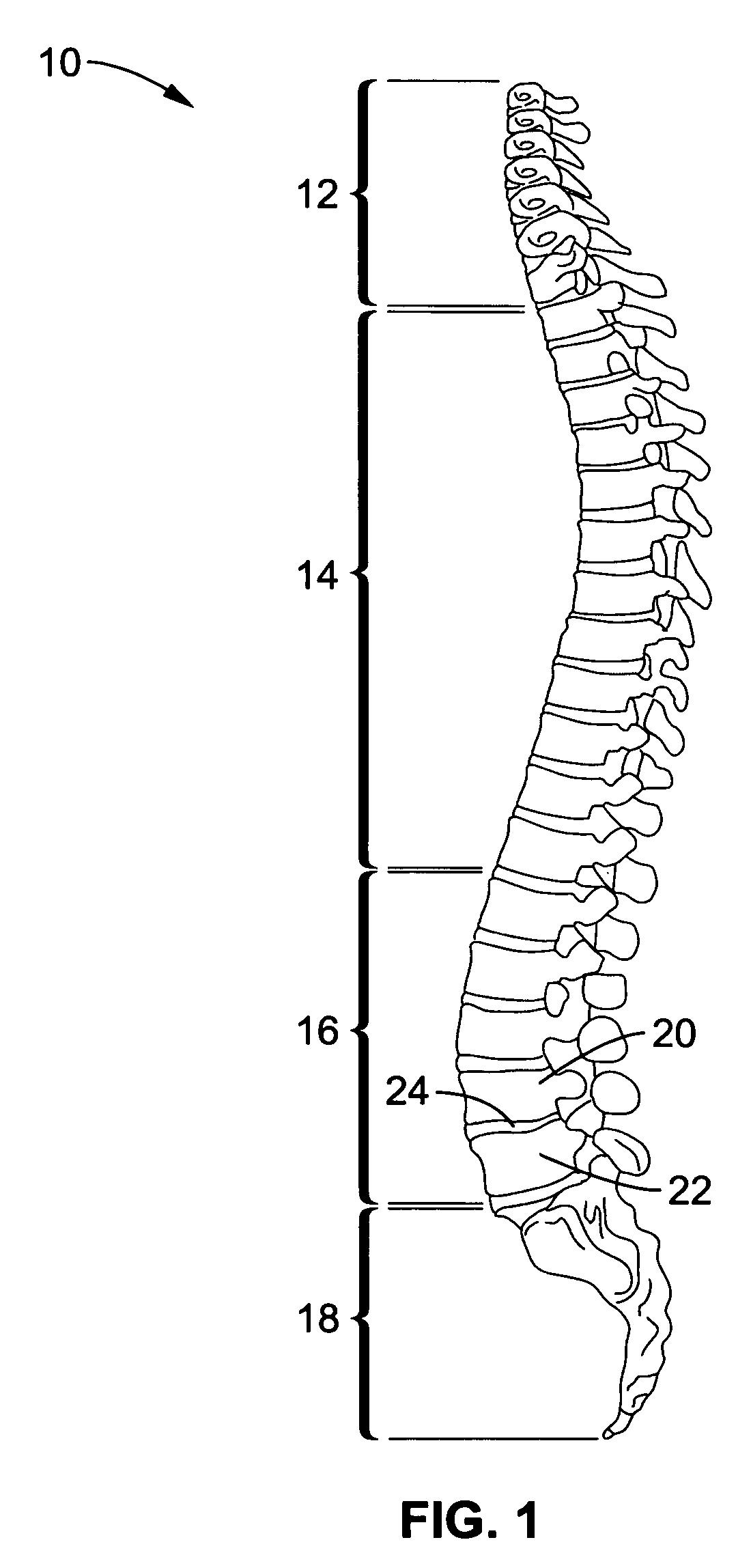
[0077]Referring to FIG. 1, a lateral view of the human spine 10 is illustrated showing the various regions of vertebrae: cervical 12, thoracic 14, and lumbar 16. The basic biomechanical unit of the spine, referred to as a motion segment, consists of two adjacent vertebrae 20, 22 and the three joint articular complex through which they move and are constrained in relation to one another.

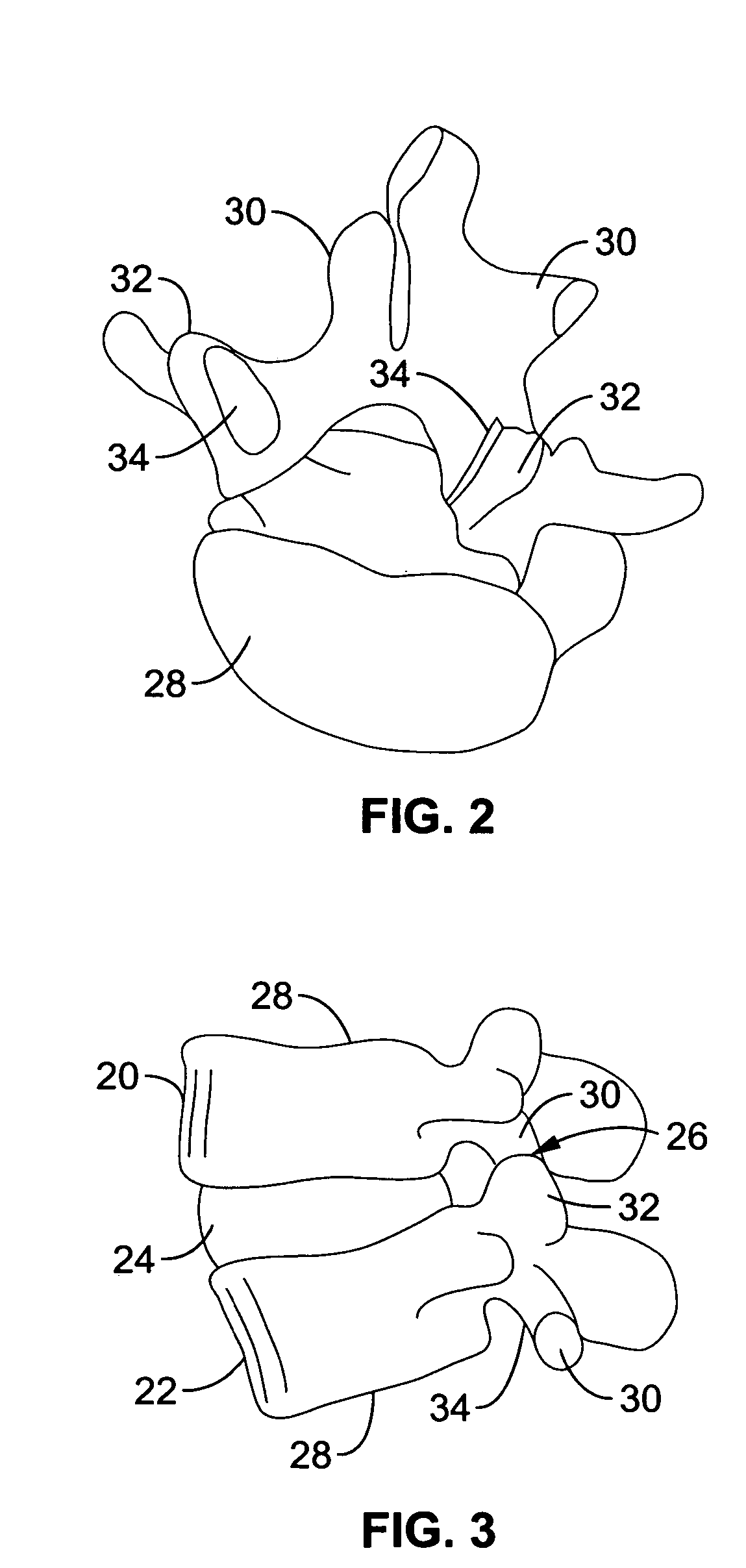
[0078]Referring to FIGS. 2 and 3, the lumbar spine articulations consist of an intervertebral disc 24 located between the bodies 28 of the adjacent vertebrae 20, 22, and two facet joints 26 symme...


PUM

PropertyMeasurementUnit
lengthaaaaaaaaaa
diameteraaaaaaaaaa
outer diameteraaaaaaaaaa

Abstract

A minimally invasive, fluoroscopically guided system is disclosed for stabilizing the articular facet joints of adjacent vertebrae. Ring and dowel implants are disclosed for installation into the facet joint. The invention includes a novel spine surgical training aid used in the initial surgeon training process for refreshing the surgeon's perspective of the critical three dimensional anatomy of the vertebrae. The invention also includes a surgical kit having a range of size-specific drills, inserters, impactors and custom-length long k-wires matched to the internal diameter of the instrumentation system.

Description

CROSS-REFERENCE TO RELATED APPLICATIONS[0001]Not ApplicableSTATEMENT REGARDING FEDERALLY SPONSORED RESEARCH OR DEVELOPMENT[0002]Not ApplicableINCORPORATION-BY-REFERENCE OF MATERIAL SUBMITTED ON A COMPACT DISC[0003]Not ApplicableNOTICE OF MATERIAL SUBJECT TO COPYRIGHT PROTECTION[0004]A portion of the material in this patent document is subject to copyright protection under the copyright laws of the United States and of other countries. The owner of the copyright rights has no objection to the facsimile reproduction by anyone of the patent document or the patent disclosure, as it appears in the United States Patent and Trademark Office publicly available file or records, but otherwise reserves all copyright rights whatsoever. The copyright owner does not hereby waive any of its rights to have this patent document maintained in secrecy, including without limitation its rights pursuant to 37 C.F.R. § 1.14.BACKGROUND OF THE INVENTION[0005]1. Field of the Invention[0006]This invention per...

Claims


Application Information

Patent Timeline
Patent Type & Authority Patents(United States)
IPC IPC(8): A61B17/70A61B17/58
CPCA61B17/1615A61B17/1637A61B17/1671A61B17/7064A61B17/92A61F2/4405A61F2/4611G09B23/30A61B2019/303A61B2019/5416A61F2/4455A61F2002/30062A61F2002/30171A61F2002/302A61F2002/3021A61F2002/30235A61F2002/30616A61F2002/30769A61F2002/30787A61F2002/30841A61F2002/30884A61F2002/30968A61F2002/4475A61F2002/4627A61F2210/0004A61F2230/005A61F2230/0065A61F2230/0067A61F2230/0069A61F2310/00023A61F2310/00131A61B2090/033A61B2090/3916A61F2002/30593
Inventor BARRY, RICHARD J.
Owner BARRY RICHARD J
Why Eureka
Try Eureka