Magnetic memory

a magnetic memory and memory technology, applied in the field of magnetic memory, can solve the problems of increasing the consumption of electric current, weakening the generated magnetic field, and no longer enabling the magneto-resistivity effect element to produce the magnetic field needed for magnetic memory, so as to reduce power consumption, enhance writing properties, and stabilize magnetic fields.

Inactive Publication Date: 2008-11-18
TDK CORPARATION
View PDF14 Cites 1 Cited by
  • Summary
  • Abstract
  • Description
  • Claims
  • Application Information

AI Technical Summary

Benefits of technology

[0014]If the thickness of the counter element side yoke is unduly small, the shortage will result in inevitably weakening the magnetic field generated in the counter element side yoke and no longer enabling the magneto-resistivity effect element to produce sufficiently the magnetic field needed for magnetic memory. If the thickness of the counter element side yoke is unduly large meanwhile, the excess will result in inevitably increasing the consumption of the electric current which is necessary for enabling the counter element side yoke to generate a magnetic field. By having this range conform to the present invention, therefore, it is made possible to establish ideal balance between the magnetic field generated in the counter element side yoke and the quantity of electric current consumed for this generation and ensure efficient writing of signal in the magneto-resistivity effect element.
[0016]By satisfying this range, the counter element yoke is enabled to have the shape thereof become narrow and long in the circumferential direction of the wire and consequently suppress the otherwise inevitable spontaneous occurrence of magnetization of (one side of) the circumferential direction of the wire inside the counter element side yoke. As a result, it is made possible to allow the magnetization generated on the outer periphery of the wire to be ideally balanced in both directions and permit the signal directed toward the magneto-resistivity effect element to be written therein efficiently at a high speed. If the counter element side yoke has an unduly long shape in the direction of extension of the wire, the excess will possibly result in inducing the formation of a magnetic domain in the counter element side yoke and preventing the change of magnetization in the yoke from proceeding smoothly (due to deterioration of response). If the element has an unduly large size, the excess will possibly result in deteriorating the responsibility of the magnetic field which is generated in consequence of the flow of electric current to the wire. When this invention is fulfilled, therefore, it is made possible to induce the generation of magnetic fields in both directions of the outer periphery of the wire efficiently with high responsibility.
[0018]If the element side yoke has an unduly small thickness, the shortage will result in rendering small the magnetic field generated from the yoke and deteriorating the writing efficiency. If it has an unduly large thickness, the excess will possibly result in forming a magnetic domain in the yoke and preventing the change of magnetization of the yoke from proceeding smoothly. When this yoke fulfills the present invention, it is enabled to concentrate the magnetic field in the magneto-resistivity effect element while ensuring retention of high responsibility.
[0021]Also, it is provided with an electric wire extended in a direction of arbitrary decision, a magneto-resistivity effect element disposed adjacently to the wire, and a yoke structure disposed along the circumferential direction of the wire and is characterized by the fact that the thickness of the counter element side yoke formed on the side opposite the magneto-resistivity effect element in the yoke structure is so set as to be larger than the thickness of the element side yoke forming the side opposite the magneto-resistivity effect element in the yoke structure. When the magnetic memory fulfills this invention, it can efficiently provide the magneto-resistivity effect element by enabling the counter element side yoke set at a large wall thickness to attain positive repression of the leakage of the magnetic field and permitting this magnetic field to be concentrated via the element side yoke set at a small wall thickness. In this case, it is preferred that the thickness of the counter element side yoke is set so as to be larger than 50 nm and smaller than 150 nm and, at the same time, the thickness of the element side yoke is set so as to be larger than 10 nm and smaller than 30 nm.
[0027]This invention is capable of stabilizing the magnetic field produced from the electric wire, smoothing the change of the magnetization in the yoke occurring in consequence of the change of the magnetic field, and manifesting the effect of enhancing the writing property while decreasing the power consumption.

Problems solved by technology

If the thickness of the counter element side yoke is unduly small, the shortage will result in inevitably weakening the magnetic field generated in the counter element side yoke and no longer enabling the magneto-resistivity effect element to produce sufficiently the magnetic field needed for magnetic memory.
If the thickness of the counter element side yoke is unduly large meanwhile, the excess will result in inevitably increasing the consumption of the electric current which is necessary for enabling the counter element side yoke to generate a magnetic field.
If the element has an unduly large size, the excess will possibly result in deteriorating the responsibility of the magnetic field which is generated in consequence of the flow of electric current to the wire.

Method used


Image

  • Magnetic memory
  • Magnetic memory
  • Magnetic memory

Examples


Embodiment Construction

[0047]Now, the mode of embodiment of the magnetic memory according to this invention will be described in detail below with reference to the accompanying drawings. In the description of the drawings, like components will be denoted by like symbols and repeated explanations will be omitted.

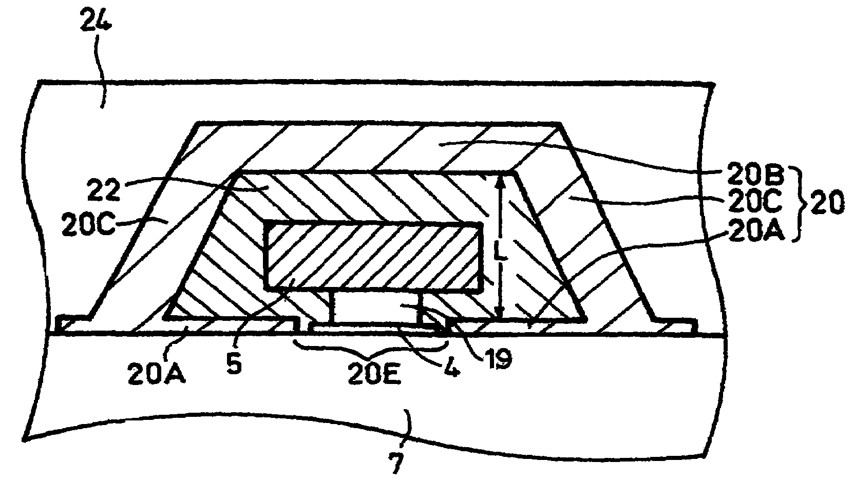
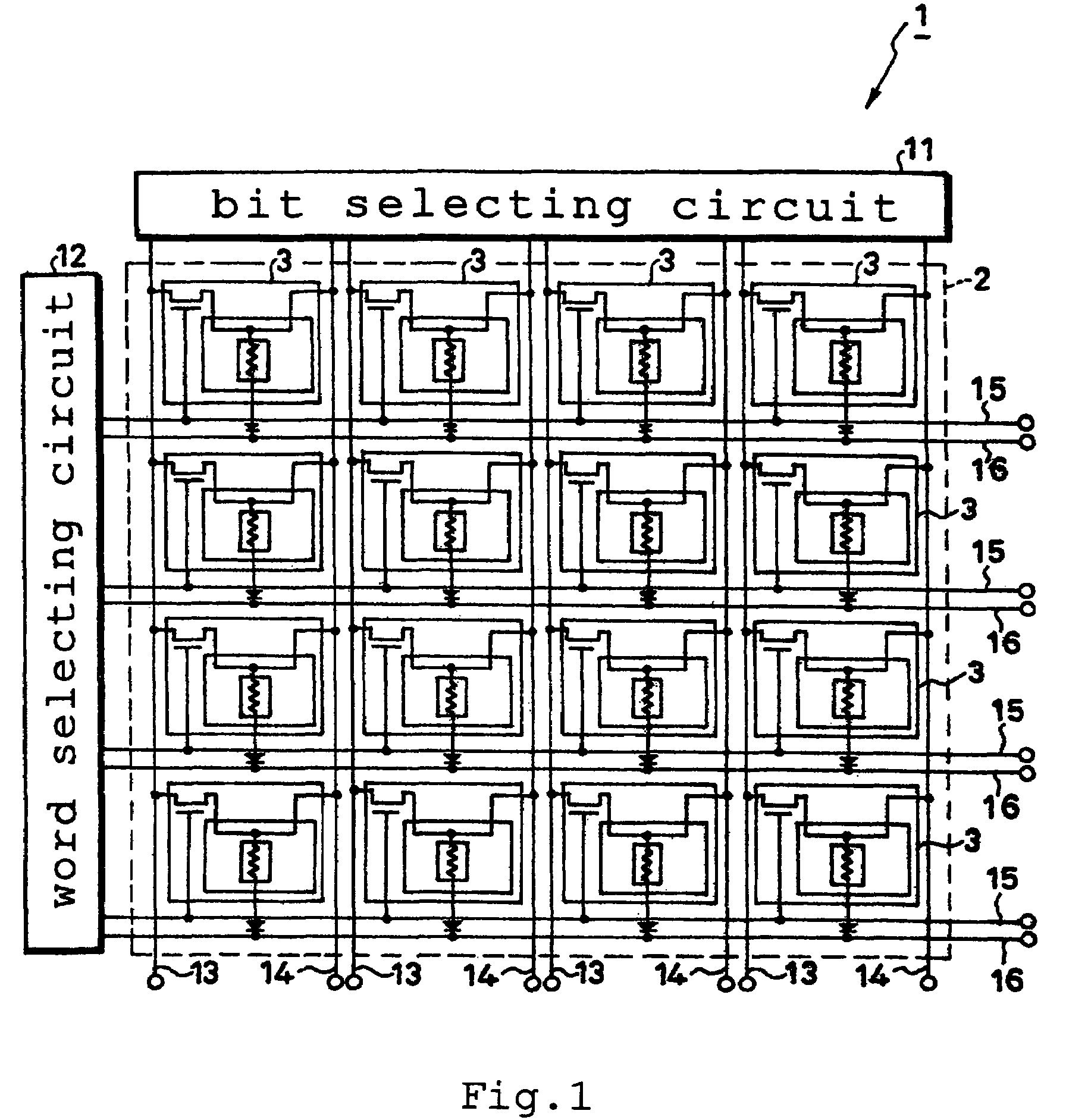
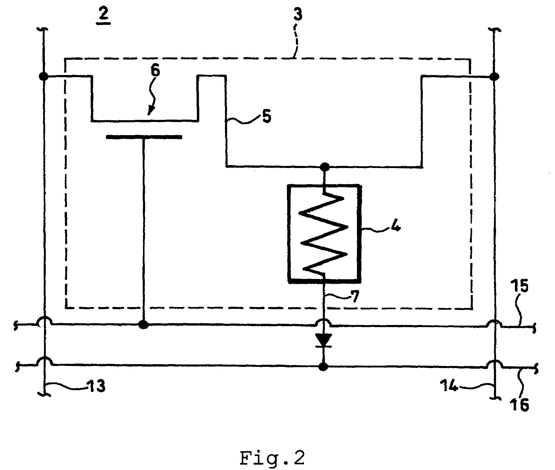
[0048]FIG. 1 is a conceptual diagram illustrating the whole structure of a magnetic memory 1 according to the first embodiment of this invention. A magnetic memory 1 is provided with a memory part 2, a bit selecting circuit 11, a word selecting circuit 12, bit lines 13 and 14, and word lines 15, 16. In the memory part 2, a plurality of memory cells 3 are two-dimensionally arrayed in m lines and n rows (m and n each denoting an integer of not less than 2). As illustrated in an enlarged scale in FIG. 2, the memory regions 3 are individually furnished with a TMR element 4, a combination reading-writing wire 5, a combination reading-writing transistor 6, a reading wire 7, a ferromagnetic yoke structure...


PUM


Abstract

A magnetic memory 1 having a wire 5 extended in a direction of arbitrary decision, an electro-resistivity effect element 4 disposed adjacently to the wire 5, and a counterelement side yoke 20B disposed adjacently on the side opposite the magneto-resistivity effect element 4 in the wire 5 and having the thickness of the counterelement side yoke 20B so set as to be larger than 50 nm and smaller than 150 nm. Owing to conformity with this invention, this magnetic memory is enabled to homogenize the magnetization property during the course of writing operation and perform the writing work with a low electric current.

Description

BACKGROUND OF THE INVENTION[0001]1. Field of the Invention[0002]This invention relates to a magnetic memory for storing information in a magneto-resistivity effect element.[0003]2. Description of the Related Art[0004]In recent years, the MRAM (Magnetic Random Access Memory) has been attracting attention as a memory cell for use in such information processing devices as computers and communication facilities. Since the MRAM is capable of memorizing data magnetically and therefore maintaining directions of magnetization without having to use any electric means, it can avoid the disadvantage of losing information due to power failure as experienced by the DRAM (Dynamic Random Access Memory) and SRAM (Static RAM) which are volatile memories. The MRAM also excels such conventional nonvolatile memories as the flash EEPROM and the hard disk device in terms of access speed, reliability, and power consumption. The MRAM, therefore, is reputed to be capable of alternating the functions of such...

Claims


Application Information

Patent Timeline
Patent Type & Authority Patents(United States)
IPC IPC(8): G11C11/00
CPCB82Y10/00G11C11/16H01L27/228H01L43/08H10B61/22H10N50/10
Inventor HARATANI, SUSUMU
Owner TDK CORPARATION
Why Eureka
Try Eureka