Magnetic memory

Inactive Publication Date: 2007-06-14
TDK CORPARATION
View PDF6 Cites 7 Cited by
  • Summary
  • Abstract
  • Description
  • Claims
  • Application Information

AI Technical Summary

Benefits of technology

[0026] Then, the magnetic memory contemplated by this invention is provided with an electric wire extended in a direction of arbitrary decision, a magneto-resistivity effect element disposed adjacently to the wire, a counter element side yoke disposed adjacently to the side opposite the magneto-resistivity effect element in the wire, an element side yoke disposed on the same side as the magneto-resistivity effect element in the wire, and a pair of lateral part yokes connecting the neighborhoods of the opposite terminals of the element side yoke and the neighborhoods of the opposite terminal

Problems solved by technology

If the thickness of the counter element side yoke is unduly small, the shortage will result in inevitably weakening the magnetic field generated in the counter element side yoke and no longer enabling the magneto-resistivity effect element to produce sufficiently the magnetic field needed for magnetic memory.
If the thickness of the counter element side yoke is unduly large meanwhile,

Method used


Image

  • Magnetic memory
  • Magnetic memory
  • Magnetic memory

Examples


Embodiment Construction

[0047] Now, the mode of embodiment of the magnetic memory according to this invention will be described in detail below with reference to the accompanying drawings. In the description of the drawings, like components will be denoted by like symbols and repeated explanations will be omitted.

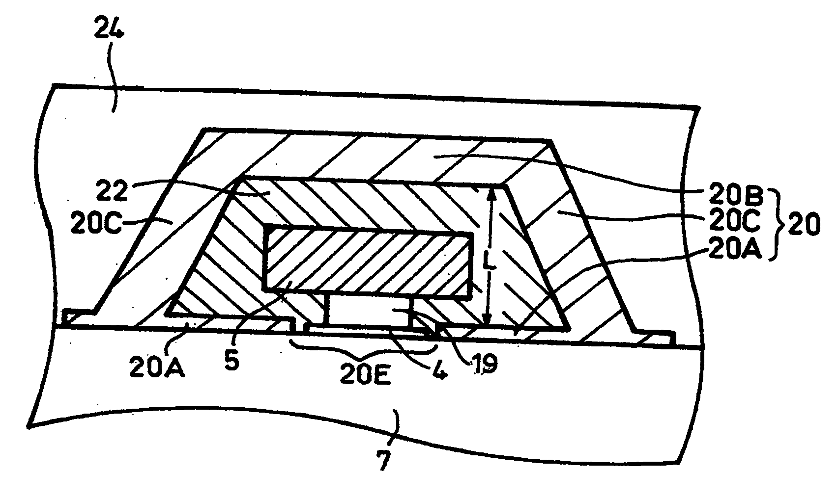
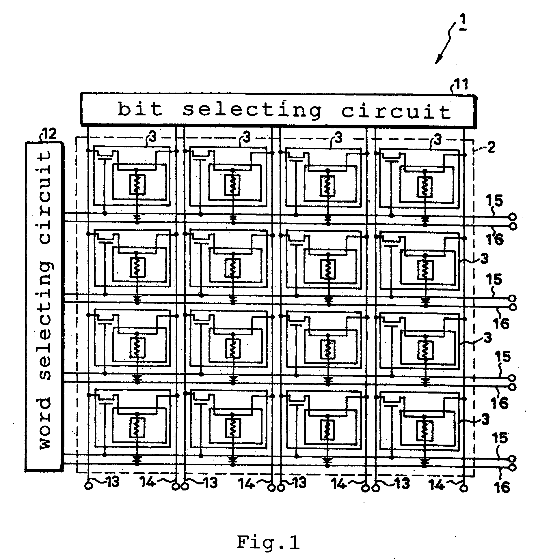
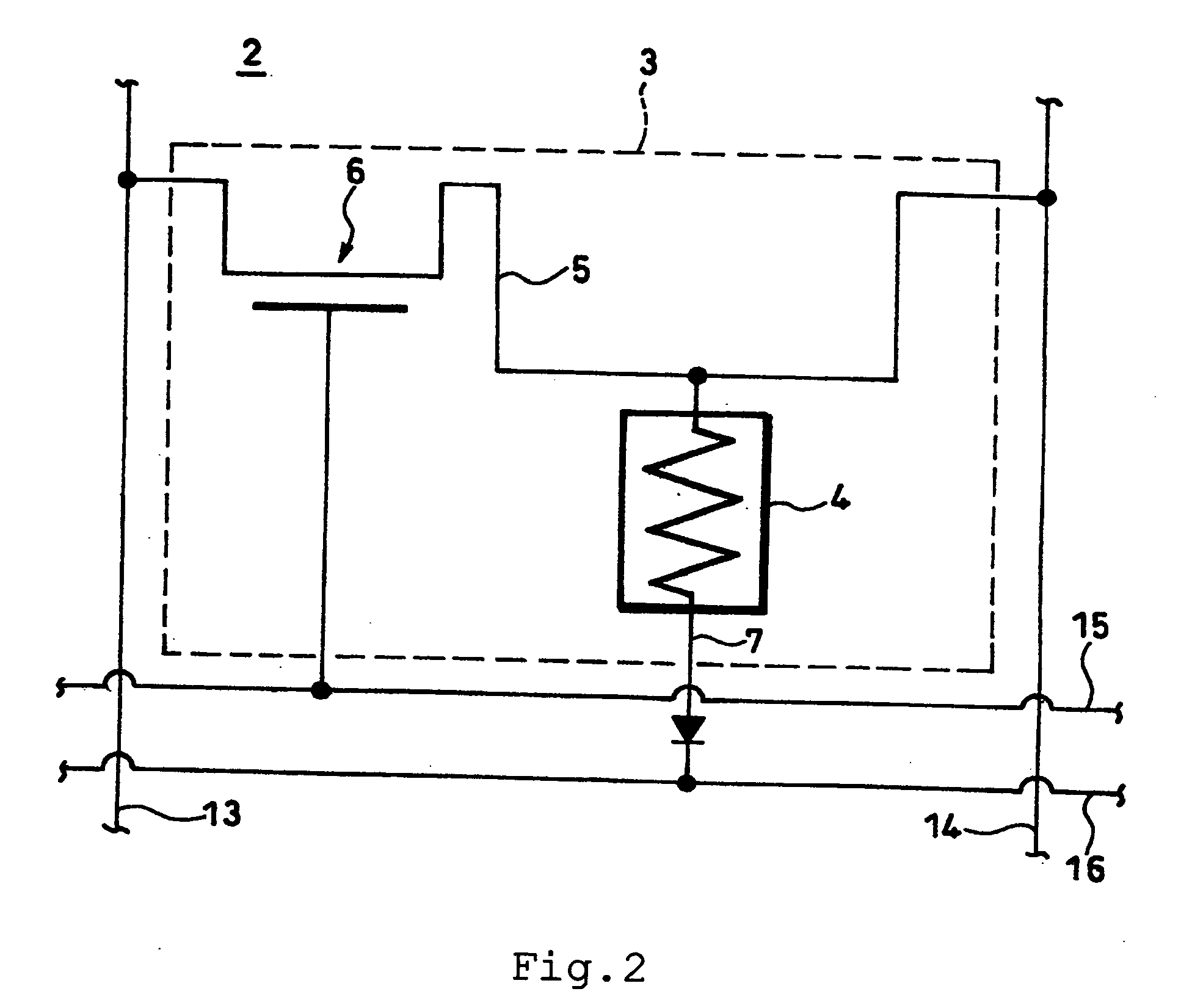
[0048]FIG. 1 is a conceptual diagram illustrating the whole structure of a magnetic memory 1 according to the first embodiment of this invention. A magnetic memory 1 is provided with a memory part 2, a bit selecting circuit 11, a word selecting circuit 12, bit lines 13 and 14, and word lines 15, 16. In the memory part 2, a plurality of memory cells 3 are two-dimensionally arrayed in m lines and n rows (m and n each denoting an integer of not less than 2). As illustrated in an enlarged scale in FIG. 2, the memory regions 3 are individually furnished with a TMR element 4, a combination reading-writing wire 5, a combination reading-writing transistor 6, a reading wire 7, a ferromagnetic yoke structu...


PUM


Abstract

A magnetic memory 1 having a wire 5 extended in a direction of arbitrary decision, an electro-resistivity effect element 4 disposed adjacently to the wire 5, and a counter element side yoke 20B disposed adjacently on the side opposite the magneto-resistivity effect element 4 in the wire 5 and having the thickness of the counter element side yoke 20B so set as to be larger than 50 nm and smaller than 150 nm. Owing to conformity with this invention, this magnetic memory is enabled to homogenize the magnetization property during the course of writing operation and perform the writing work with a low electric current.

Description

BACKGROUND OF THE INVENTION [0001] 1. Field of the Invention [0002] This invention relates to a magnetic memory for storing information in a magneto-resistivity effect element. [0003] 2. Description of the Related Art [0004] In recent years, the MRAM (Magnetic Random Access Memory) has been attracting attention as a memory cell for use in such information processing devices as computers and communication facilities. Since the MRAM is capable of memorizing data magnetically and therefore maintaining directions of magnetization without having to use any electric means, it can avoid the disadvantage of losing information due to power failure as experienced by the DRAM (Dynamic Random Access Memory) and SRAM (Static RAM) which are volatile memories. The MRAM also excels such conventional nonvolatile memories as the flash EEPROM and the hard disk device in terms of access speed, reliability, and power consumption. The MRAM, therefore, is reputed to be capable of alternating the functions...

Claims


Application Information

Patent Timeline
IPC IPC(8): G11C11/00
CPCB82Y10/00G11C11/16H01L27/228H01L43/08H10B61/22H10N50/10
Inventor HARATANI, SUSUMU
Owner TDK CORPARATION
Why Eureka
Try Eureka