Compensating method for writing power of optic disc driver

A technology of optical disc drive and compensation method, which is applied in the direction of optical recording/reproduction, optical recording/reproduction/erasing method, instrument, etc., can solve the problems of cost and volume increase, and achieve the effect of good writing power

Inactive Publication Date: 2007-06-27
LEJIN GUANGDIAN ELECTRONIC CO LTD SHANGHAI
View PDF0 Cites 2 Cited by
  • Summary
  • Abstract
  • Description
  • Claims
  • Application Information

AI Technical Summary

Problems solved by technology

[0004] However, at present, the temperature around the light sensor can be detected only by installing an additional IC such as a thermal variable resistor and an ADC as described above. Therefore, the cost and volume are increased, which is a disadvantage.

Method used


Image

  • Compensating method for writing power of optic disc driver
  • Compensating method for writing power of optic disc driver
  • Compensating method for writing power of optic disc driver

Examples


Embodiment Construction

[0019] Embodiments of the method for compensating writing power of an optical disc drive according to the present invention will be described in detail below with reference to the accompanying drawings.

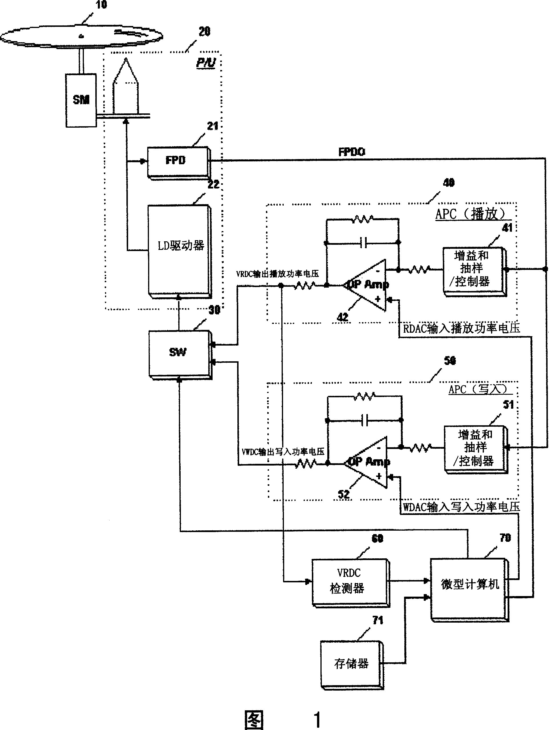
[0020] FIG. 1 is a schematic diagram showing the composition of an optical train of an optical disc drive according to a writing power compensation method of an optical disc drive of the present invention. It is composed of the following parts: it is composed of gain and sampling / controller 41 and OP amplifier 42, and plays the automatic power control (APC) of outputting the playing power voltage (VRDC) according to the input FPDO signal and the input playing power voltage (RDAC). ) circuit 40; composed of gain and sampling / controller 51 and OP amplifier 52, write automatic power control (APC) according to input FPDO signal and input write power voltage (WDAC) output write power voltage (VWDC) Circuit 50; Output the LD driver 22 of the light beam corresponding to the playback...


PUM


Abstract

This invention relates to a compensation method for write-in power of a disk drive including: 1, testing out the input signal of a power control circuit and comparing output signals to compare them with a primary value, in which, the power control circuit can emit drive signals of the laser diode, 2, if the difference of the tested value and the primary value exceeds the sphere based on the compared result, then the write-in power is compensated, which can test the ambient temperature of an optical sensor based on the output voltage of the R / F internal played APC circuit with a certain input voltage even if there are not fittings such as thermal resistors.

Description

technical field [0001] The present invention relates to the technology of the write power compensation method of the optical disk drive. The automatic power control (APC: Automatic Power Control) circuit inside the R / F automatically detects the temperature around the optical sensor, and the write power is compensated accordingly. Background technique [0002] In order to improve the writing quality, the writing power should be properly compensated as the temperature around the photosensor changes. [0003] For this reason, at present, an integrated circuit (Chip-Type) such as a thermal variable resistor (Thermistor) is mainly used to directly detect the temperature around the light sensor, convert this value to ADC (analog-to-digital conversion), and then use this ADC value to properly adjust the temperature. Write power is compensated. [0004] However, at present, only by installing an additional IC such as a thermistor and an ADC, the temperature around the photosensor c...

Claims


Application Information

Patent Timeline
Patent Type & Authority Applications(China)
IPC IPC(8): G11B7/00G11B7/0045G11B7/125G11B7/126
Inventor 郑万泳柳承澔
Owner LEJIN GUANGDIAN ELECTRONIC CO LTD SHANGHAI
Why Eureka
Try Eureka