
Loudspeaker having cooling system

a technology of loudspeaker and cooling system, which is applied in the direction of transducer details, electrical transducers, electrical apparatus, etc., can solve the problems of reducing the efficiency and performance of the loudspeaker, increasing the resistance of the voice coil, and affecting the sound quality of the loudspeaker, so as to achieve efficient heat dissipation, low distortion effect, and increase cooling efficiency

Inactive Publication Date: 2007-09-18
ALPINE ELECTRONICS INC
View PDF10 Cites 9 Cited by
  • Summary
  • Abstract
  • Description
  • Claims
  • Application Information

AI Technical Summary

Benefits of technology

[0012]It is, therefore, an object of the present invention to provide a loudspeaker having an improved cooling system while minimizing distortions of sound.
[0013]It is another object of the present invention to provide a loudspeaker having a shorting ring coupled with a heat dissipation plate, thereby stabilizing magnetic field and efficiently dissipating heat.
[0014]It is a further object of the present invention to provide a method and structure for assembling the cooling system having the shorting ring and the heat dissipation plate in the loudspeaker.

Problems solved by technology

For a loudspeaker described above, heat within the loudspeaker and distortion of sound can be problematic.
As an example of disadvantage, it has been found that significant temperature rise increases the resistance of the voice coil.
This, in turn, results in a substantial portion of the input power of the loudspeaker to be converted to the heat, thereby lowering the efficiency and performance of the loudspeaker.
In particular, it has been found that increased resistance of the voice coil in the loudspeaker can lead to non-linear loudness compression effects at high sound levels.
Further, significant temperature rise can melt bonding materials in the voice coil or overheat the voice coil, resulting in permanent structural damage to the loudspeaker.
However, this arrangement does not, by itself, provide an efficient cooling mechanism.

Method used


Image

  • Loudspeaker having cooling system
  • Loudspeaker having cooling system
  • Loudspeaker having cooling system

Examples


Embodiment Construction

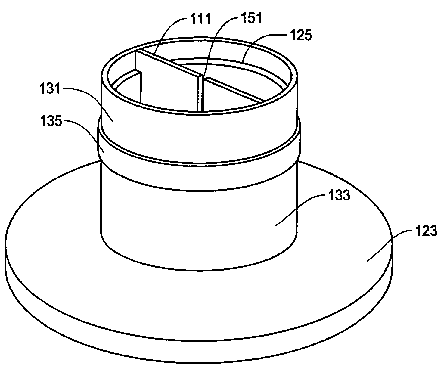
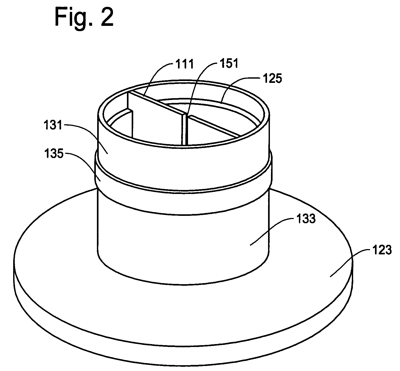
[0037]The loudspeaker of the present invention is provided with a shorting ring and a heat dissipation plate thermally connected with one another to establish a cooling system for dissipating heat generated by the loudspeaker. A shorting ring in a magnetic circuit has been proposed to improve an impedance characteristics of a loudspeaker. The cooling system of the present invention makes use of the shorting ring to improve the sound quality as well as to promote heat dissipation in combination with the heat dissipation plate. Because of the shorting ring and the heat dissipation plate, the loudspeaker of the present is able to efficiently dissipate the heat, and at the same time, to minimize distortion of the sound by compensating the impedance characteristic.

[0038]The effect and structure of the shorting ring is described, for example, in U.S. Pat. No. 5,815,587 and Japanese Patent Laid-Open Publication No. 11-168797. One of the main effect of the shorting ring is that the magnetic...


PUM


Abstract

A loudspeaker has a cooling system in which a pole piece has a shorting ring made of non-magnetic conductive material that stabilizes magnetic field to reduce distortion of sound and a heat dissipation plate that couples to the shorting ring to facilitate efficient dissipation of heat. The heat generated by a voice coil of the loudspeaker is transmitted to the shorting ring and is conducted to the heat dissipation plate which acts as a heat sink to allow the heat dissipation. A multiplicity of shorting rings may be provided to further reduce impedance modulation, each of which is coupled to the heat dissipation plate. The heat dissipation plate has a gap in an axial direction of the loudspeaker to prevent an electric current in the shorting ring from flowing through the heat dissipation plate.

Description

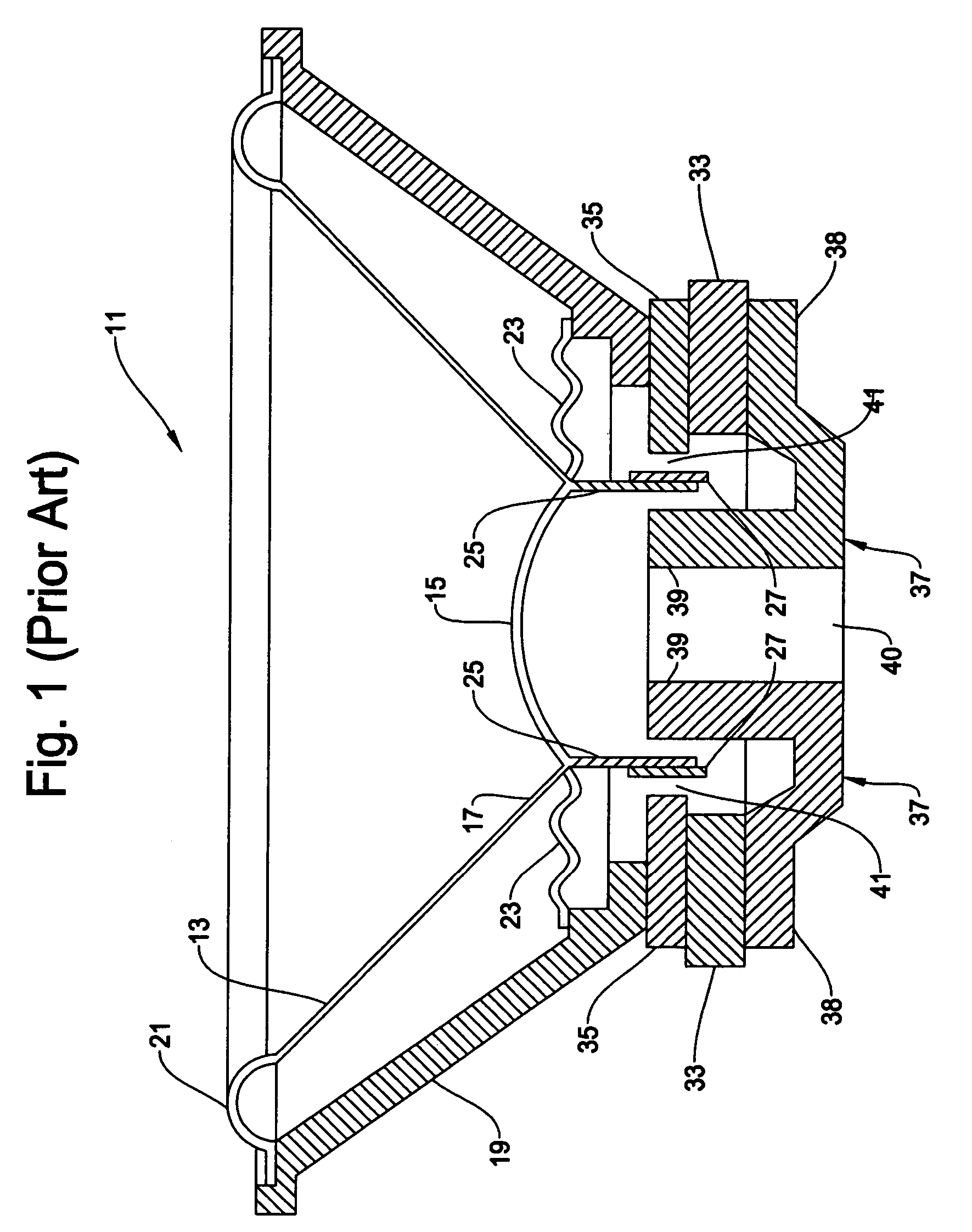
FIELD OF THE INVENTION[0001]This invention relates to a loudspeaker having a cooling system, and more particularly, to a loudspeaker with a shorting ring and a heat dissipation plate thermally connected with each other for efficient heat dissipation while reducing distortion in sound by improving impedance characteristic of the loudspeaker.BACKGROUND OF THE INVENTION[0002]Loudspeakers, or speakers, are well known in the art and are commonly used in a variety of applications, such as in home theater stereo systems, car audio systems, indoor and outdoor concert halls, and the like. A loudspeaker typically includes an acoustic transducer comprised of an electro-mechanical device which converts an electrical signal into acoustical energy in the form of sound waves and an enclosure for directing the sound waves produced upon application of the electrical signal.[0003]An example of structure in the conventional loudspeaker is shown in FIG. 1. The loudspeaker 11 includes a speaker cone 13 ...

Claims


Application Information

Patent Timeline
Patent Type & Authority Patents(United States)
IPC IPC(8): H04R1/00H04R11/02H04R9/06
CPCH04R9/022
Inventor KEMMERER, JASONTRUE, ROBERT
Owner ALPINE ELECTRONICS INC
Learn More