Leg support arrangement for operating tables

a technology for operating tables and legs, applied in rigid tables, medical science, surgery, etc., can solve the problem that the free space between the spread leg supports is not sufficient for all applications, and achieve the effect of quick and easy connection

Active Publication Date: 2008-11-25
MAQUET GMBH
View PDF3 Cites 23 Cited by
  • Summary
  • Abstract
  • Description
  • Claims
  • Application Information

AI Technical Summary

Benefits of technology

[0010]The inventive solution has the advantage that both the folding axes for the upper leg supports as well as the folding axes for the lower leg supports both maintain their orientation in space when the leg supports are moved away from or toward one another. It is therefore assured that the lower leg supports upon angularly adjusting the leg supports, that is upon the upward pivoting of the upper leg support and the folding down of the lower leg support, these do not become inclined. Thereby a sliding of the lower leg laterally from the lower leg support is inhibited.
[0013]Preferably the connecting piece is insertable into a receiver fixed to the operating table, which receiver is a part of the folding hinge for the upper leg support. Therefore the leg plates can be quickly and easily connected to the base element or removed from it and, as the case may be, may be exchanged for other leg supports.

Problems solved by technology

Although as a rule recesses are provided on the edges of the leg supports facing one another near the base element, the free space existing between the spread leg supports is not sufficient for all applications.

Method used


Image

  • Leg support arrangement for operating tables
  • Leg support arrangement for operating tables
  • Leg support arrangement for operating tables

Examples


Embodiment Construction

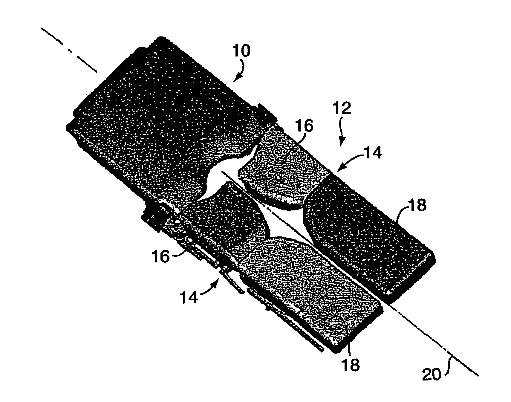
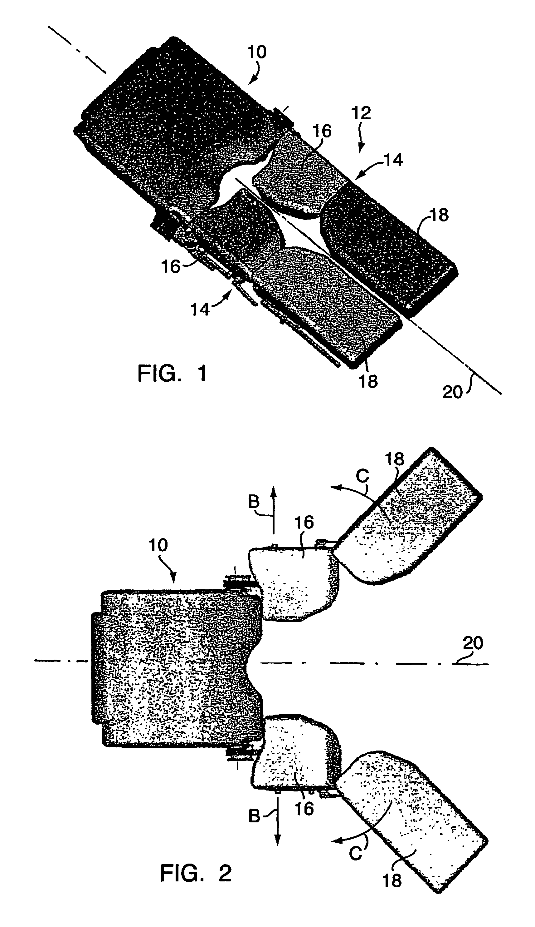
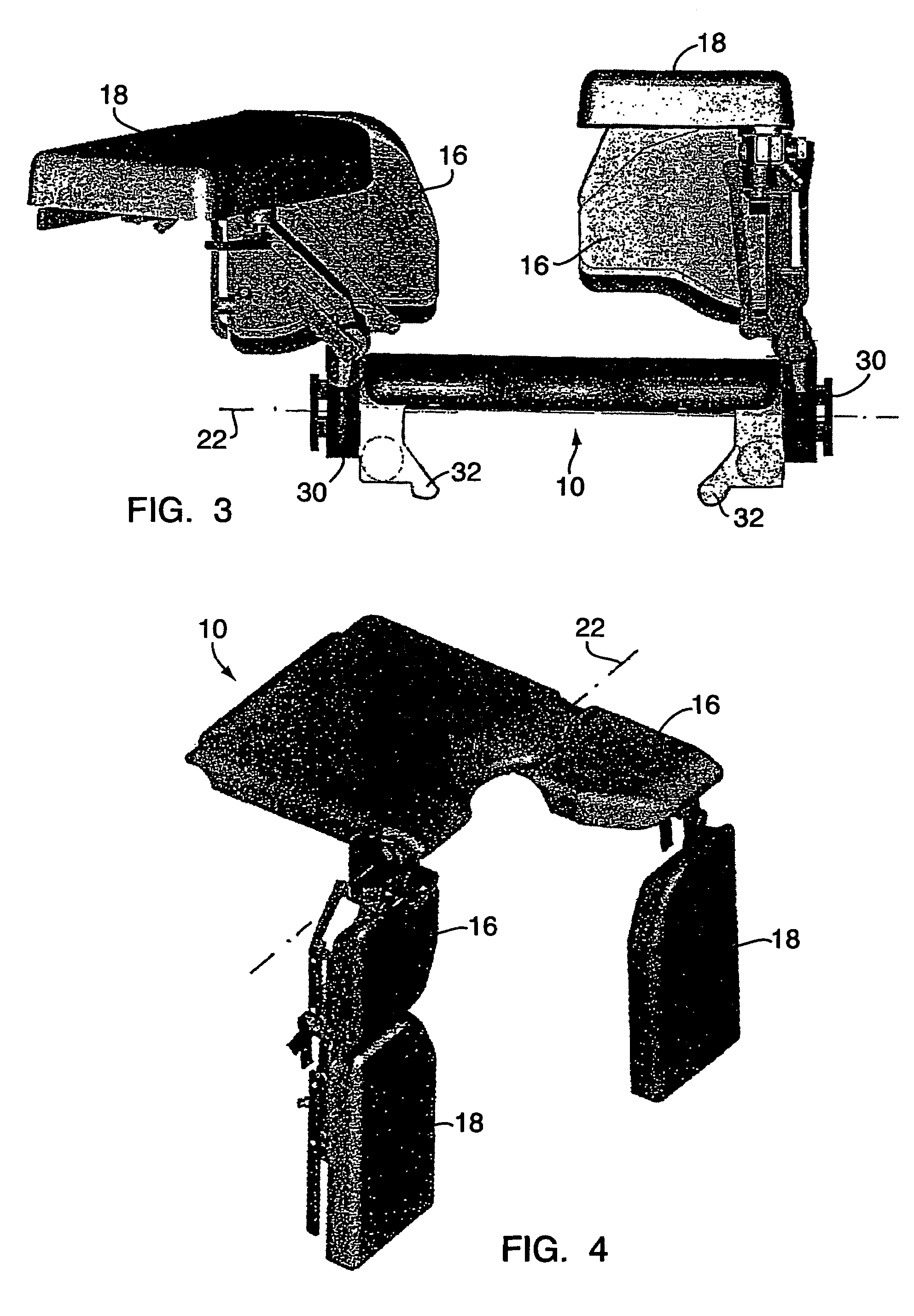
[0022]Illustrated in FIG. 1 is a portion of a patient support surface or operating table plate with a base element 10, which element is usually connected to or connectable to the column head of a support column of an operating table. Connected with the base element 10 is a leg support arrangement 12 having two leg supports 14. Each leg support 14 has an upper leg support 16 and a lower leg support 18. The upper leg supports 16 are connected with the base element 10 and lower leg supports 18 are connected with the associated upper leg supports 16 by way of joints so that the upper leg supports 16 and the lower leg supports 18 can be adjusted to different positions. FIG. 1 shows the leg supports 12 and their parts 16, 18 in a fundamental position in which the leg supports 12 are oriented parallel to the longitudinal middle axis 20 of the operating table plate and lie close to one another. FIG. 2 shows the arrangement according to FIG. 1 in a spread position, in which the upper leg sup...


PUM


Abstract

The invention relates to a leg support arrangement for operating tables comprising two leg supports, connected to a base element of an operating table such that, the above are adjustable between a base position, lying adjacent to each other parallel to the longitudinal mid-axis of the operating table and a spread position with a separation from the longitudinal mid-axis, whereby each leg support is connected to the base element by means of a parallelogram joint, the joint axes (36, 52, 44, 54) of which are arranged perpendicular to the plane of the base element.

Description

CROSS REFERENCE TO RELATED APPLICATIONS[0001]Applicants hereby claim foreign priority benefits under 35 U.S.C. § 119 of PCT Patent Application No. PCT / EP2003 / 010844 filed Sep. 30, 2003 and German Patent Application No. 102 53 906.5 filed Nov. 19, 2002, the disclosures of which are herein incorporated by reference.BACKGROUND OF THE INVENTION[0002]1. Technical Field[0003]The invention concerns a leg support arrangement for operating tables with two leg supports connected with a base element of an operating table so that they are adjustable between a fundamental position in which they lie next to one another parallel to the longitudinal middle axis of the operating table and a spread position in which they are spaced from the longitudinal middle axis of the operating table.[0004]2. Background Art[0005]In all operating procedures in which the operator moves into the foot-end of the operation field the legs of the patient lying on the operating table must be spread. In customary operatin...

Claims


Application Information

Patent Timeline
Patent Type & Authority Patents(United States)
IPC IPC(8): A61G13/00A61G13/12
CPCA61G13/1245
Inventor KOCH, GUIDOKATZENSTEIN, BERNHARD
Owner MAQUET GMBH
Why Eureka
Try Eureka