
Hydraulic control valve with integrated dual actuators

a control valve and actuator technology, applied in the direction of lift valves, valve details, functional valve types, etc., can solve the problems of increasing flow through the valve, unable to inspect the seal or the diaphragm without dismantling the valve, and sliding piston seals or flat or rolling diaphragms being subject to ware and eventual failur

Active Publication Date: 2008-11-25
BERMAD CS LTD
View PDF12 Cites 6 Cited by
  • Summary
  • Abstract
  • Description
  • Claims
  • Application Information

AI Technical Summary

Problems solved by technology

The sliding piston seals or the flat or rolling diaphragms used are subject to ware and eventual failure due to movement and aging.
Failure causes pressure loss from the control chamber, which usually causes the control valve itself to fail to the open position, that is, the main valve member moves to the fully raised position, which causes flow through the valve to increase, with consequent problems arising upstream or downstream depending on the application of the valve.
Because the sliding seals or diaphragm are contained within the valve itself and are not visible from the outside, inspection of the seals or diaphragm without dismantling the valve is usually impossible, and thus there is a tendency to replace the seals or diaphragm prematurely rather than risk failure in normal use.
Also, the control systems used to control the valves can fail, for example, due to blockage of a conduit with dirt, or failure of the pilot control valve to control properly, and thus, in very critical areas preventative maintenance costs can be considerable.
While the failure of these valves can prevent damage in some applications, when they fail there is a complete cessation of flow through the valve, which in some applications can create other dangerous situations.
Other valves use a parallel duplicate or redundant system in which both systems have some duplicating components which are operative simultaneously, and both are subject to wear, usually at the same rate, and thus are likely to fail at approximately similar moments in time.
Although the Singer valves are more compact and economical than the parallel duplicate or redundant systems, they are still much larger than regular single actuator valves.

Method used


Image

  • Hydraulic control valve with integrated dual actuators
  • Hydraulic control valve with integrated dual actuators
  • Hydraulic control valve with integrated dual actuators

Examples


Embodiment Construction

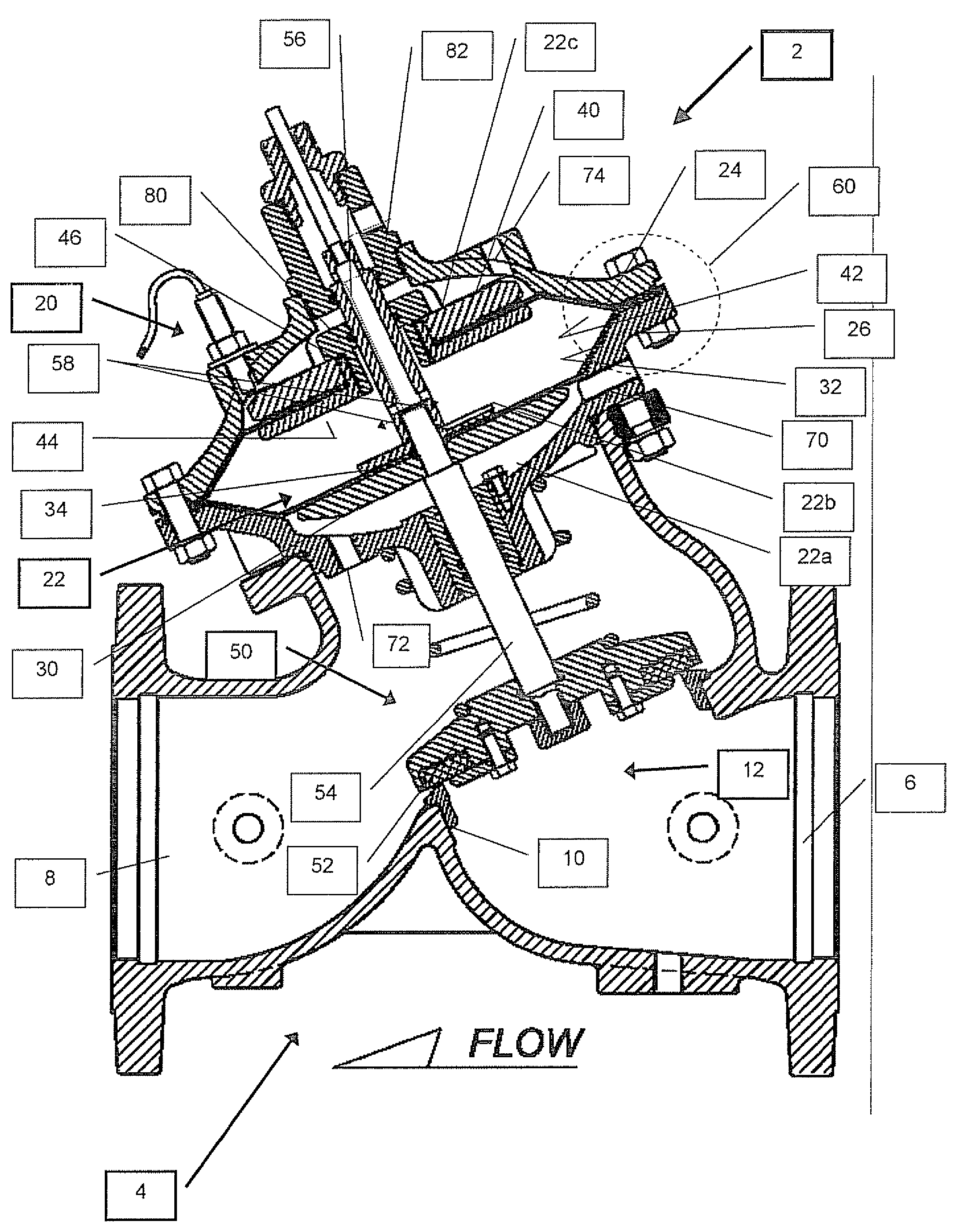
[0036]The present invention is a control valve with integrated dual actuators in which both of the actuators are deployed in a single, common control chamber.

[0037]The principles and operation of control valve according to the present invention may be better understood with reference to the drawings and the accompanying description.

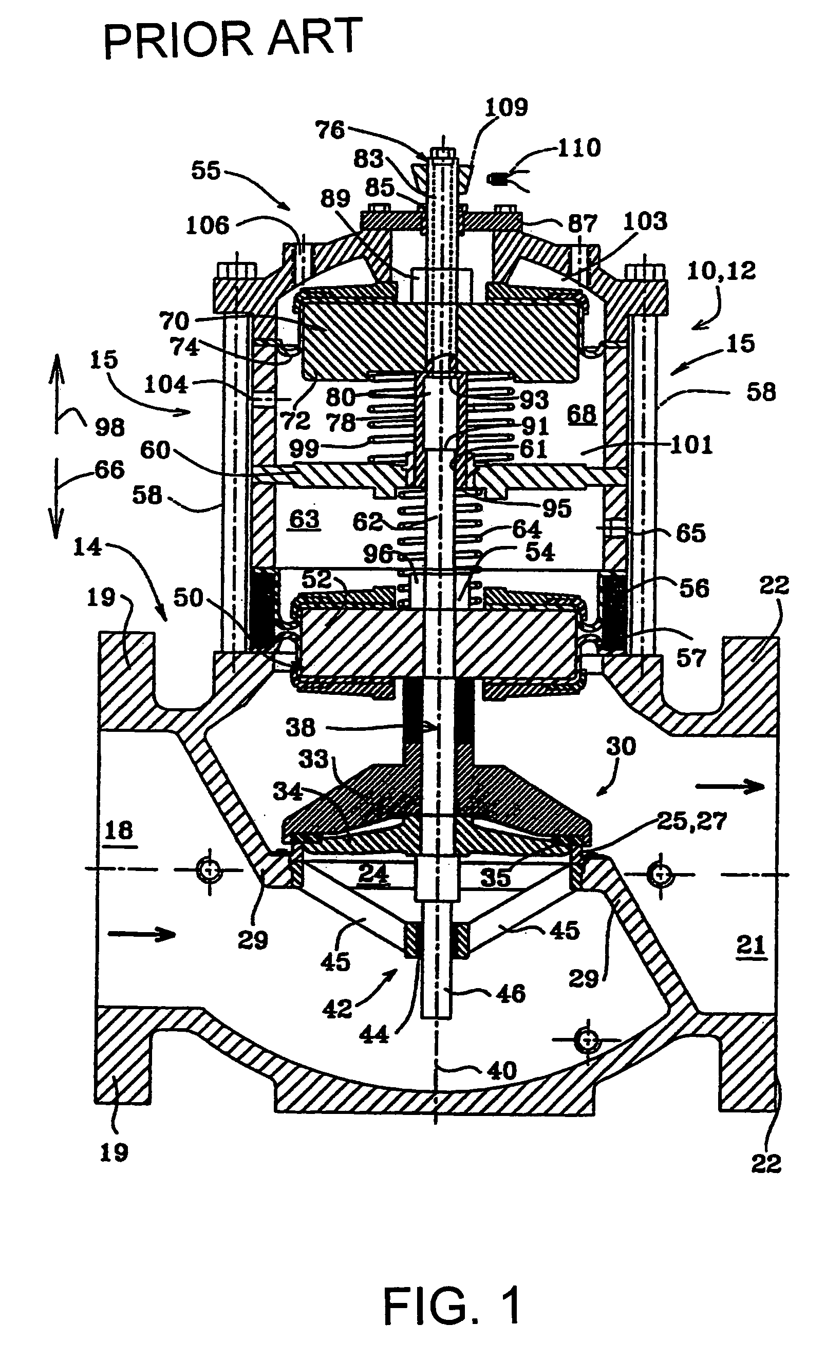
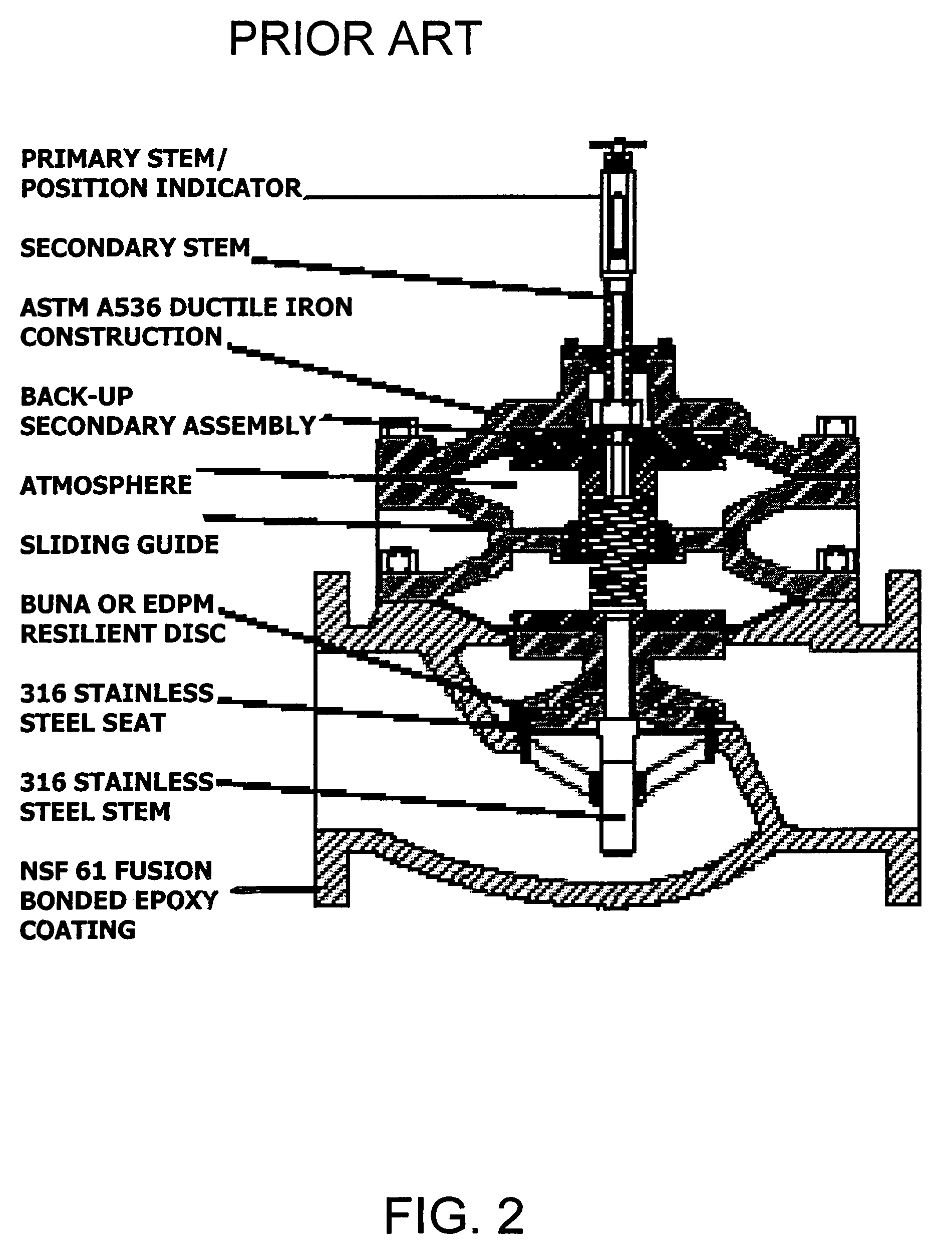
[0038]By way of introduction, unlike the dual actuator valves of prior art, in which each actuator is deployed in a separate control chamber (see FIGS. 1 and 2), the dual actuator valve of the present invention, as illustrated in FIGS. 3-6, deploys both the primary and secondary actuator elements in a single, common control chamber. Therefore, the present invention provides a dual actuator valve having dimensions that are the same as, or similar to, the dimensions of a single actuator control valve. It will be appreciated that the actuator elements may be of diaphragm type or piston type actuator elements. As used herein, a dual actuator valve having dime...


PUM


Abstract

The dual actuator valve of the present invention deploys both the primary and secondary actuator elements in a single, common control chamber. Therefore, the present invention provides a dual actuator valve having dimensions that are the same as, or similar to, the dimensions of a single actuator control valve. It will be appreciated that the actuator elements may be of diaphragm type or piston type actuator elements. The primary actuator element is mechanically linked to the valve plug and regulates the flow though the valve, while the secondary actuator element remains in a fully open position. Should the primary actuator element fail to operate the valve due, for example, to diaphragm rupture, failure of the primary control system, or any other reason, the secondary control system activates the secondary actuator element, which then effects movement of the primary actuator element thereby resuming flow regulation or closure of the valve as necessary.

Description

FIELD AND BACKGROUND OF THE INVENTION[0001]The present invention relates to automatic flow control valves and, in particular, it concerns a control valve with integrated dual actuators in which both of the actuators are deployed in a single, common control chamber.[0002]Automatic control valves are known to utilize piston type actuators, or diaphragm type actuators having either a flat or rolling flexible diaphragm, as the drive mechanism for displacing the valve plug. The sliding piston seals or the flat or rolling diaphragms used are subject to ware and eventual failure due to movement and aging. Failure causes pressure loss from the control chamber, which usually causes the control valve itself to fail to the open position, that is, the main valve member moves to the fully raised position, which causes flow through the valve to increase, with consequent problems arising upstream or downstream depending on the application of the valve. Because the sliding seals or diaphragm are co...

Claims


Application Information

Patent Timeline
Patent Type & Authority Patents(United States)
IPC IPC(8): F16K31/00F01B21/02F16K1/00
CPCF16K31/1268
Inventor WEINGARTEN, ZVI
Owner BERMAD CS LTD
Learn More