Circuit arrangement having protective circuit and modification apparatus

a technology of circuit arrangement and protective circuit, applied in the direction of light source, light apparatus, instruments, etc., to achieve the effect of reliably preventing filament and lamp breakag

Active Publication Date: 2008-11-25
PATENT TREUHAND GESELLSCHAFT FUR ELECTRIC GLUEHLAMPEN MBH
View PDF3 Cites 0 Cited by
  • Summary
  • Abstract
  • Description
  • Claims
  • Application Information

AI Technical Summary

Benefits of technology

[0004]The present invention is therefore based on the object of developing the circuit arrangement mentioned initially such that filament and lamp breakages can be reliably prevented when using one and the same protective circuit for different lamp types.
[0006]The disadvantage with the mentioned protective circuit consists in the fact that the threshold value is not variable but is fixed in the ASIC. Even when other conceivable operational parameters of the lamp are evaluated, for example the peak value and the DC component of the lamp voltage, a threshold fixed in the protective circuit would rule out use of one and the same protective circuit for different lamp types. The present invention is based in particular on the knowledge that, owing to suitable signal processing upstream of the protective circuit, it is possible in a simple manner to adapt to the respective lamp type, which on the one hand leads to prevention of oversensitivity or lack of sensitivity in the end-of-life disconnection and on the other hand allows for the universal use of one and the same protective circuits for different lamp types.
[0011]Furthermore, the modification apparatus preferably has an interface in order to make it possible for an operator to input at least one parameter for the modification, i.e. in order to specify the type of modification. It is thus possible to adapt to the respective lamp type in a simple manner. As an alternative, modification apparatuses matched to the respective lamp types can be provided without such an interface.

Problems solved by technology

The disadvantage with the mentioned protective circuit consists in the fact that the threshold value is not variable but is fixed in the ASIC.

Method used


Image

  • Circuit arrangement having protective circuit and modification apparatus
  • Circuit arrangement having protective circuit and modification apparatus
  • Circuit arrangement having protective circuit and modification apparatus

Examples


Embodiment Construction

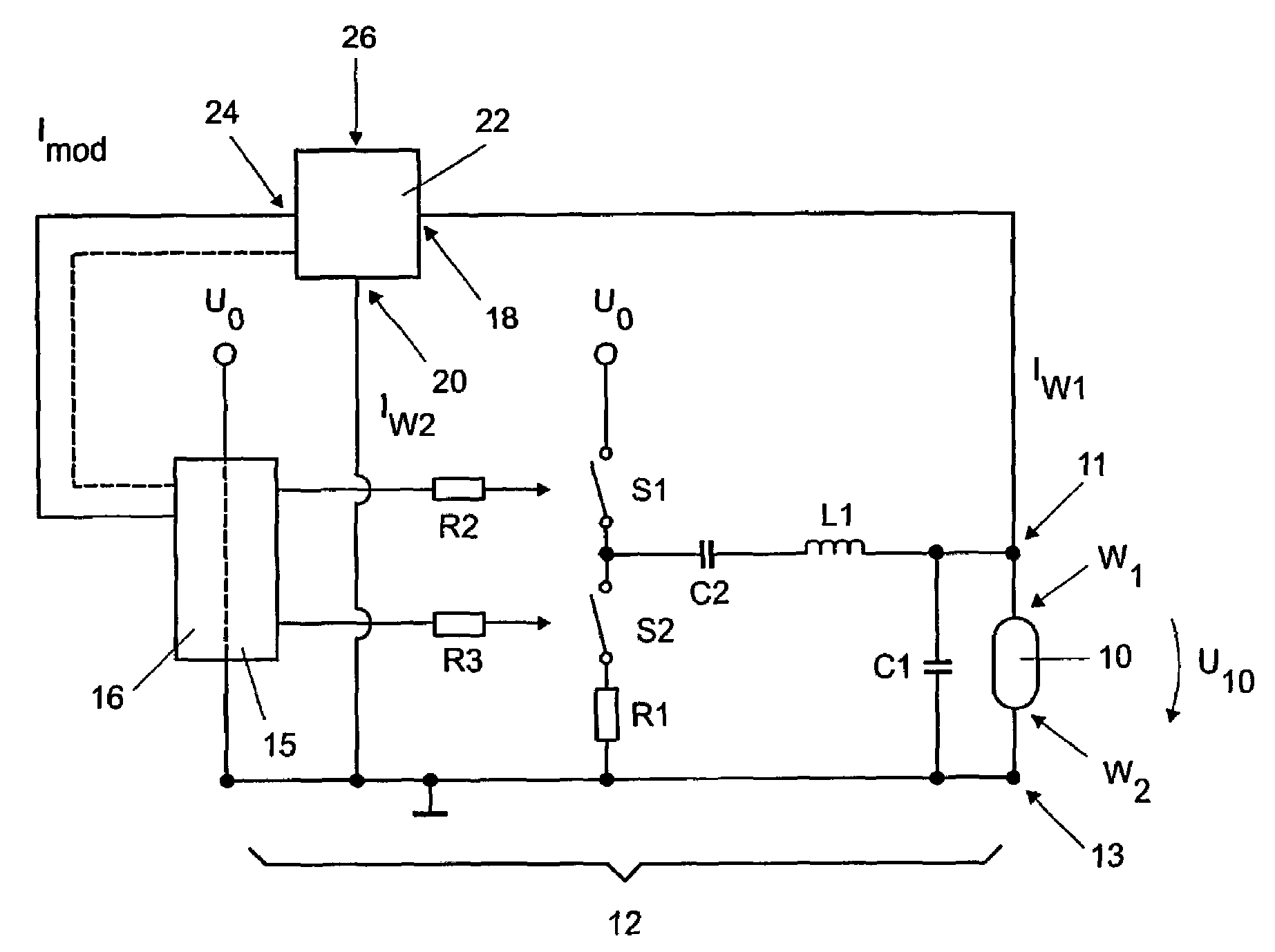
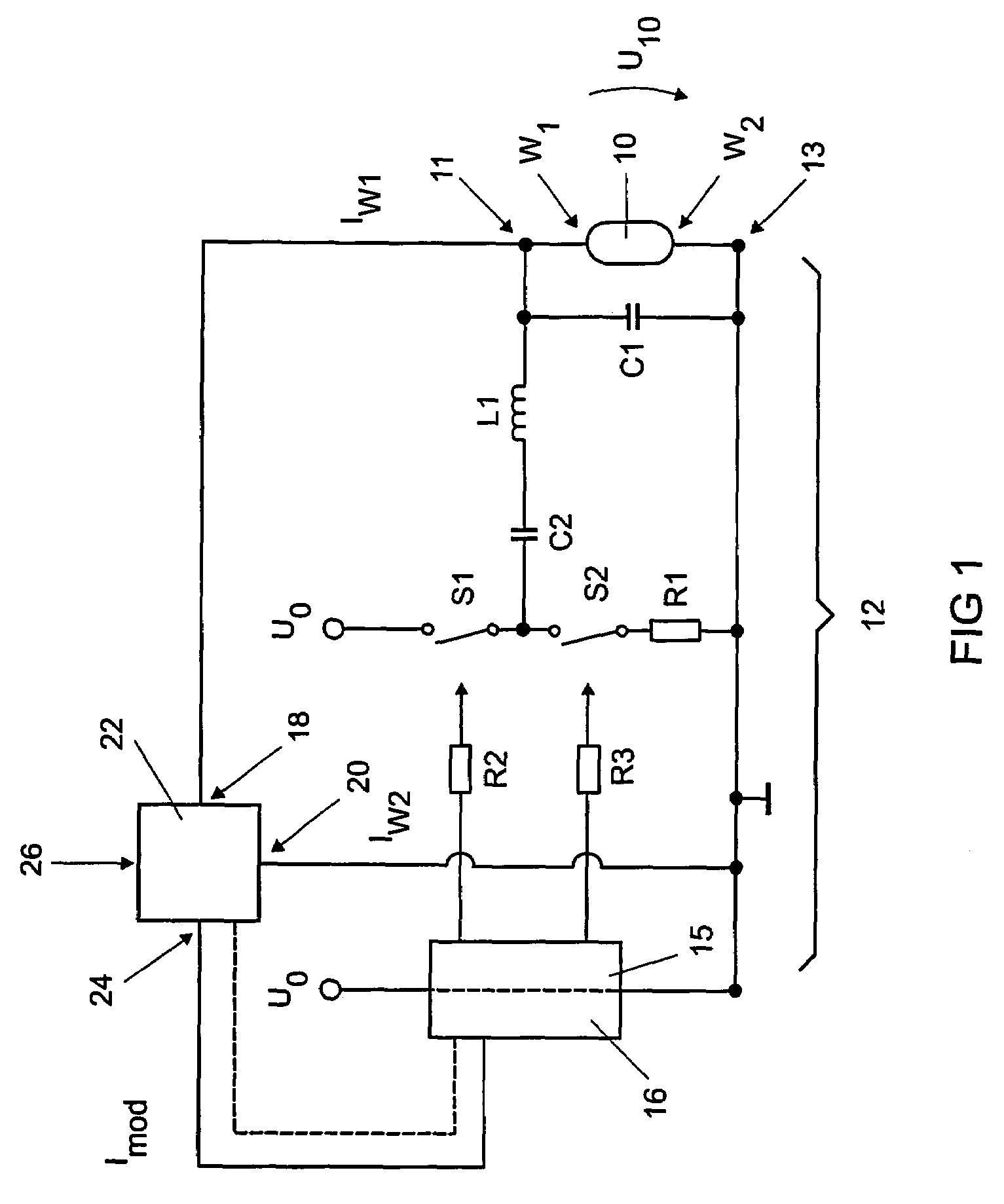
[0016]FIG. 1 shows one exemplary embodiment of a circuit arrangement according to the invention. Components which are insignificant in the terms of the invention and have long been known to those skilled in the art have been omitted for reasons of improved clarity. FIG. 1 shows a lamp 10, which is connected in parallel with a resonant capacitor C1. A connection, which is connected to a first filament W1 of the lamp 10, is identified by the reference 11. A second connection, which is connected to the second filament W2 of the lamp 10, bears the reference 13.

[0017]The series circuit comprising a coupling capacitor C2 and an inductance L1 is arranged in series with the parallel circuit comprising the lamp 10 and the resonant capacitor C1. Said coupling capacitor C2 and inductance L1 are connected to the center point of a half-bridge circuit, which comprises the switches S1 and S2. While the switch S1 is coupled to a supply voltage U0, the switch S2 is connected to ground via a resistor...


PUM


Abstract

A circuit arrangement has a drive circuit for a lamp having a first connection for a first filament of the lamp and a second connection for a second filament of the lamp, a protective circuit, coupled on the output side to the drive circuit and on the input side to the first connection for the first filament and the second connection for the second filament such that a first signal correlated with an operational parameter of the first filament, and a second signal, correlated with an operational parameter of the second filament, can be transmitted to the protective circuit. The arrangement also includes a modification apparatus connected between the protective circuit and the first connection and / or the second connection, the apparatus designed to modify the first signal and / or the second signal and to make them available to the protective circuit as a modified first signal and / or a modified second signal.

Description

FIELD OF THE INVENTION[0001]The present invention relates to a circuit arrangement having a drive circuit for a lamp having a first connection for a first filament of the lamp and a second connection for a second filament of the lamp, a protective circuit, which is coupled on the output side to the drive circuit and on the input side to the first connection for the first filament of the lamp and the second connection for the second filament of the lamp such that a first signal, which is correlated with an operational parameter of the first filament, and a second signal, which is correlated with an operational parameter of the second filament, can be transmitted to the protective circuit.BACKGROUND OF THE INVENTION[0002]Such a circuit arrangement is known. A brief explanation will be given in order to illustrate the problem on which the invention is based: The present invention is concerned with the end-of-life problem of lamps having two filament electrodes. Owing to an inhomogeneou...

Claims


Application Information

Patent Timeline
Patent Type & Authority Patents(United States)
IPC IPC(8): H05B37/00
CPCH05B41/2985
Inventor HECKMANN, MARKUSSIEGMUND, THOMAS
Owner PATENT TREUHAND GESELLSCHAFT FUR ELECTRIC GLUEHLAMPEN MBH
Why Eureka
Try Eureka