LCD driver device

a driver device and driver technology, applied in the field of lcd driver devices, can solve the problems of increased current consumption and achieve the effects of reducing disturbance of displayed images, increasing current consumption, and keeping current consumption extremely low

Inactive Publication Date: 2008-11-25
ROHM CO LTD
View PDF10 Cites 2 Cited by
  • Summary
  • Abstract
  • Description
  • Claims
  • Application Information

AI Technical Summary

Benefits of technology

[0009]An object of the present invention is to provide an LCD driver device that operates with reduced disturbance of the displayed image immediately after display is started on an LCD and that achieves this without unduly increasing current consumption.
[0011]In this circuit configuration, when no display is effected, the operation of the individual circuits is stopped to keep current consumption extremely low. When display is effected, immediately after the start of operation, the capacitive element for smoothing the display voltage is charged also by the supply voltage. This helps shorten the period required for the display voltage to reach the prescribed level after the display voltage generating circuit starts operating.
[0012]In this circuit configuration, the display voltage may be prevented from being supplied to the panel driver, or the panel driver may be prevented from operating, at least for the period required after the display voltage generating circuit starts operating until the display voltage reaches the prescribed voltage. This permits the display voltage to reach the prescribed level in a relatively short period after the display voltage generating circuit starts operating, and makes it possible to start driving the LCD once the display voltage reaches the prescribed level.
[0013]The period for which the charge circuit is kept operating may be set to be equal to the period required for the display voltage to reach the prescribed level with the charge circuit operating. This helps minimize the required period without increasing ineffective electric power consumption due to current that flows through the resistors after the display voltage generating circuit starts operating and even after all the display voltages have reached the prescribed voltages.

Problems solved by technology

Inconveniently, this results in disturbance of the displayed image immediately after display is started on the LCD.
This period can be shortened by driving the display voltages with higher capacity, but this leads to increased current consumption.

Method used


Image

  • LCD driver device
  • LCD driver device
  • LCD driver device

Examples


first embodiment

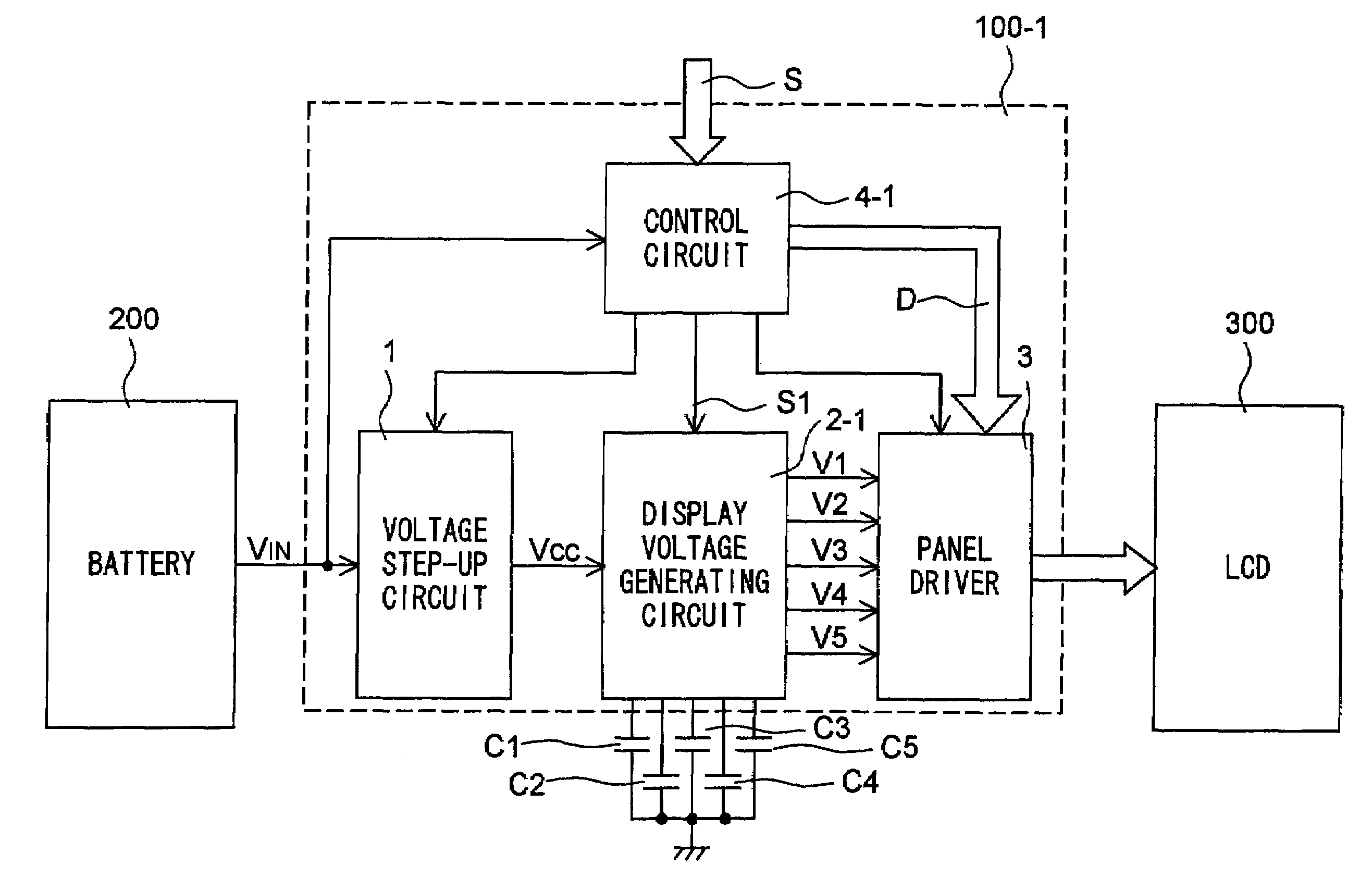
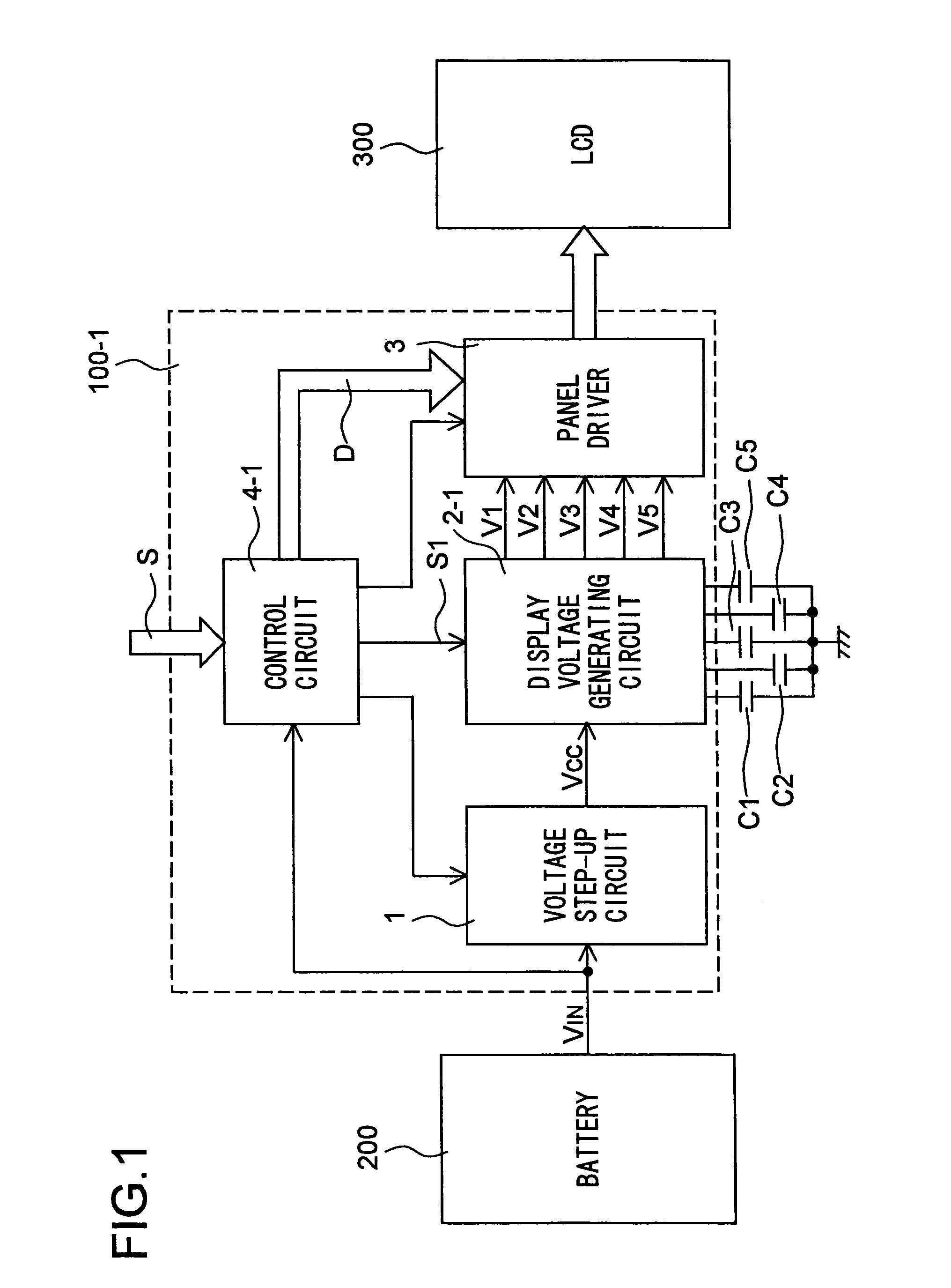
[0028]Moreover, in the first embodiment, each capacitor is charged with the supply voltage VCC for the period that is assumed to be required for the corresponding display voltage to reach the prescribed level after the display voltage generating circuit 2-1 starts operating. This makes it possible to minimize the required period without increasing ineffective electric power consumption due to current that flows through the capacitors after the display voltages V1, V2, V3, V4, and V5 have reached the prescribed levels.

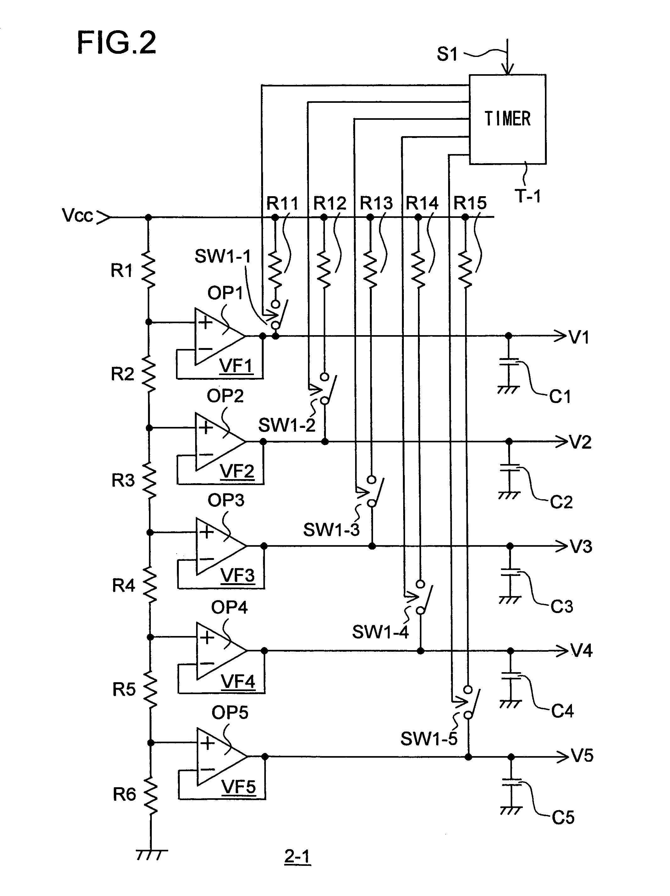
[0029]FIG. 3(b) shows how the individual output voltages rise to the prescribed voltages V1, V2, V3, V4, and V5 and behave thereafter when the resistors R11 to R15 are given the same resistance. In this case, each output voltage takes a different length of time to reach the prescribed level. Accordingly, the switch corresponding to each output voltage is turned off with different timing.

[0030]If all of the first group of switches are turned off simultaneously after all ...

second embodiment

[0039]Moreover, in the second embodiment, each capacitor is charged with the supply voltage VCC for the period that is assumed to be required for the corresponding display voltage to reach the prescribed level after the display voltage generating circuit 2-2 starts operating. This makes it possible to minimize the required period without ineffective electric power consumption before display is started on the LCD 300.

[0040]When display is stopped, all of the second group of switches are turned off when the supply of electric power to the display voltage generating circuit 2-2 is shut off. At the start of operation, the second-group switches are turned on one by one as the corresponding first-group switches are turned off one after another. Alternatively, all of the second group of switches may be turned on simultaneously when all of the first group of switches have been turned off. This helps simplify the configuration of the timer T-2. Since the display voltages are not supplied to ...


PUM

PropertyMeasurementUnit
voltageaaaaaaaaaa
display voltages V1aaaaaaaaaa
thresholdaaaaaaaaaa

Abstract

A display voltage generating circuit (2-1) for generating display voltages needed to drive an LCD has switches (SW1-1 to SW1-5), of which each has one end connected to one of capacitors (C1 to C5) for smoothing display voltages (V1 to V5) and has the other end connected through one of resistors (R11 to R15) to a supplied voltage (VCC). By an output from a timer (T-1), the switches are kept on for a predetermined period after electric power starts being supplied, so that the capacitors are charged with the supply voltage.

Description

[0001]This is a continuation application of prior application Ser. No. 10 / 130,766, filed on May 23, 2002, now U.S Pat. No. 6,844,867 which is incorporated by reference herein in its entirety.TECHNICAL FIELD[0002]The present invention relates to an LCD driver device incorporating a display voltage generating circuit for generating a display bias voltage (hereinafter referred to also as a “display voltage”) needed to effect display on an LCD (liquid crystal display).BACKGROUND ART[0003]As shown in a typical block diagram in FIG. 6, an LCD driver device 100 is composed of a voltage step-up circuit 1, a display voltage generating circuit 2, a panel driver 3, and a control circuit 4 built around a CPU or the like. The voltage step-up circuit 1 steps up a voltage VIN supplied from a battery 200 to VCC and outputs the stepped-up voltage. From the voltage VCC output from the voltage step-up circuit 1, the display voltage generating circuit 2 produces, for example, five display voltages V1, ...

Claims


Application Information

Patent Timeline
Patent Type & Authority Patents(United States)
IPC IPC(8): G09G3/36G02F1/133G09G3/20
CPCG09G3/3696G09G2330/022G09G2330/026G09G3/36
Inventor YAMADA, KOUJI
Owner ROHM CO LTD
Why Eureka
Try Eureka