Multiple door joining assembly

a technology for joining assemblies and doors, applied in the direction of door/window fittings, wing operation mechanisms, constructions, etc., can solve problems such as unnecessary impact on doors

Inactive Publication Date: 2008-12-02
BRONNER DAN
View PDF9 Cites 40 Cited by
  • Summary
  • Abstract
  • Description
  • Claims
  • Application Information

AI Technical Summary

Benefits of technology

[0007]Accordingly, the above problems and difficulties are avoided by the present invention which provides a joining hardware assembly for “ganging” their respective doors together such that by pulling or pushing on one door causes the other doors to follow. The “ganging” of the doors together employs a connecting plate and a spacer plate screwed to the bottom of a primary door while the connecting plate includes a cam follower or bearing located in such a manner as to ride in a groove in the bottom of a first secondary door. In this manner, both doors are “ganged” together. If a third or second secondary door is required to be joined with the previous two doors, a connecting angle plate is employed for securing to the s

Problems solved by technology

If this track is not present, the doors are allowed to swing independently with respect to each other which raises several problems.
One of the problems resides in that the doors are allowed to swing or bang with respect to each other and the doors may al

Method used


Image

  • Multiple door joining assembly
  • Multiple door joining assembly
  • Multiple door joining assembly

Examples


Embodiment Construction

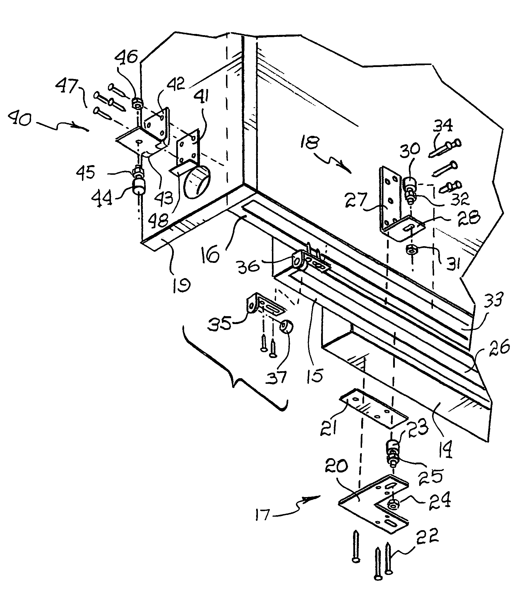
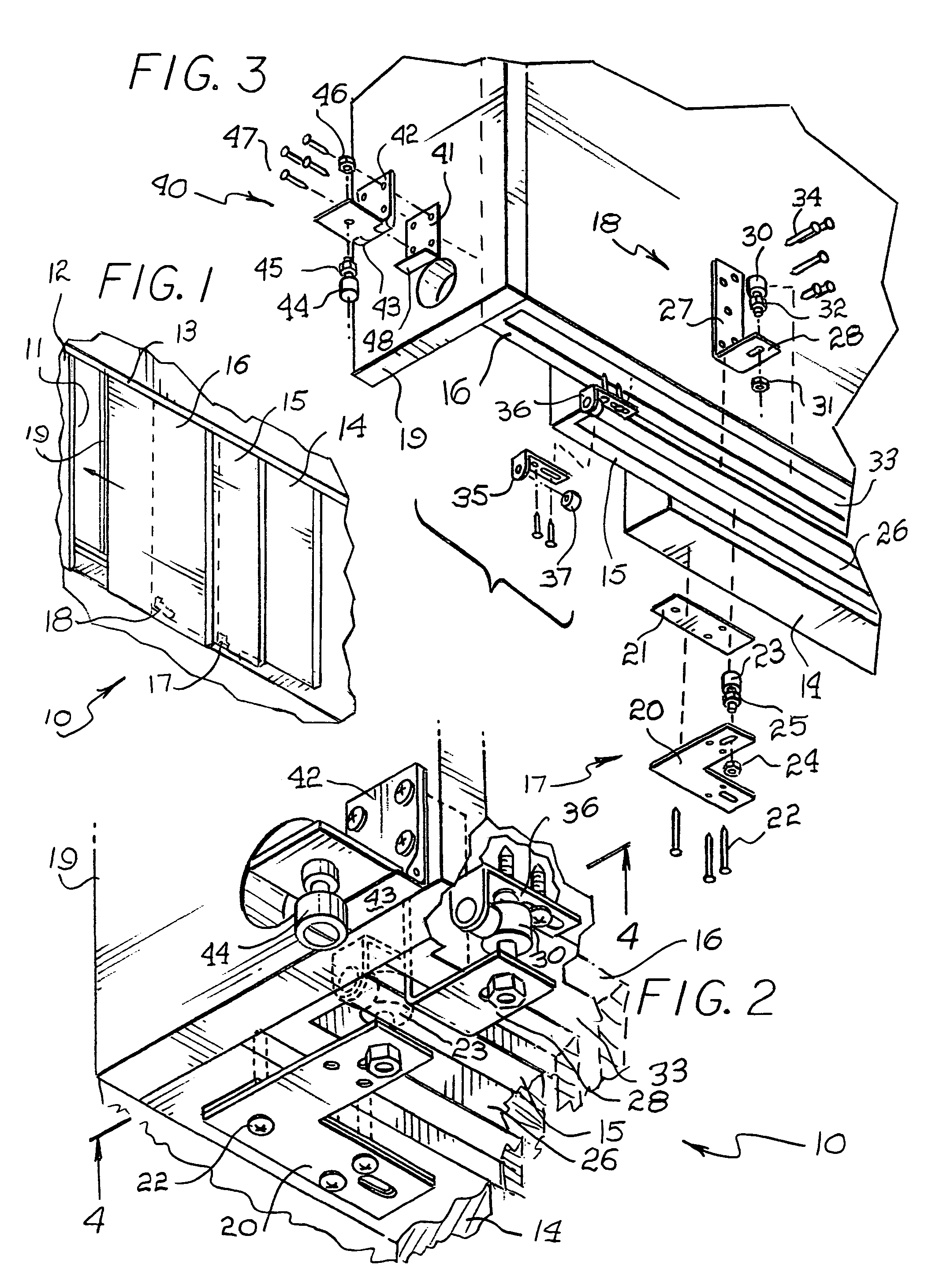
[0022]Referring to FIG. 1, the novel multi-door push / pull hardware incorporating the present invention is illustrated in the general direction of arrow 10. Typically, multi-slide door units are stored in a pocket 11 within a wall 12 of a dwelling. The door units require a head track 13 mounted in the wall 12 from which the door units downwardly depend. The door units include rollers (not shown) carried in the track 13 and the door units are identified as a primary door 14, which represents the door that is first pulled outward from the pocket 11. Secondary doors 15 and 16 are “ganged” with the primary door 14 so that as the primary door 14 is pulled along the head track 13, the secondary doors will follow in sequence and unison. It is to be particularly noted that the door units are rollably suspended from the head track 13 and there is no floor or bottom track to which the bottom of the door units are secured or stabilized. Normally, in the absence of a floor track, the door units ...


PUM


Abstract

A joining assembly for “ganging” respective doors together such that by movement of one door causes the other doors to follow. A connecting plate and a spacer plate is screwed to the bottom of a primary door while the connecting plate includes a cam follower to ride in a groove in the bottom of a first secondary door. In this manner, both doors are “ganged” together. If other secondary doors are required to be joined with the previous two doors, a connecting angle plate is employed for securing to the secondary door so as to guide the third, fourth, etc. doors. A guide stop, hinge floor guide, and cam follower assembly is mounted to the last door in the multi-door series and the cam follower “tracks” in a floor guide hidden in a “pocket” when a storage pocket is employed in the installation. By ganging these doors, stability is imparted by the weight and mass of the doors.

Description

[0001]Priority Claimed on Ser. No. 60 / 525,155 filed Nov. 28, 2003BACKGROUND OF THE INVENTION[0002]1. Field of the Invention[0003]The present invention relates to the field of multiple door joining or attachment assemblies and more particularly to such an attachment assembly that allows the joining and stabilizing of two or more doors with or without a floor mounted track so that when a primary door is moved, a secondary door or doors will follow as well.[0004]2. Brief Description of the Prior Art[0005]Conventionally, multiple door installations, such as pocket doors and multi-slide door units, require a track located in the floor below the doors to guide and stabilize the doors as the doors are opened or closed. If this track is not present, the doors are allowed to swing independently with respect to each other which raises several problems. One of the problems resides in that the doors are allowed to swing or bang with respect to each other and the doors may also swing out of the ...

Claims


Application Information

Patent Timeline
IPC IPC(8): E05D15/06
CPCE05D15/0656E05D15/08E05F17/004E05Y2201/684E05Y2600/46E05Y2900/14E05Y2800/122E05Y2900/00
Inventor BRONNER, DAN
Owner BRONNER DAN
Why Eureka
Try Eureka