LED lamp with a heat sink

Inactive Publication Date: 2008-12-02
FU ZHUN PRECISION IND SHENZHEN +1
View PDF3 Cites 145 Cited by
  • Summary
  • Abstract
  • Description
  • Claims
  • Application Information

AI Technical Summary

Problems solved by technology

This issue has become a challenge for engineers to design the LED illumination, i.e. the LED lamp.

Method used


Image

  • LED lamp with a heat sink
  • LED lamp with a heat sink
  • LED lamp with a heat sink

Examples


Embodiment Construction

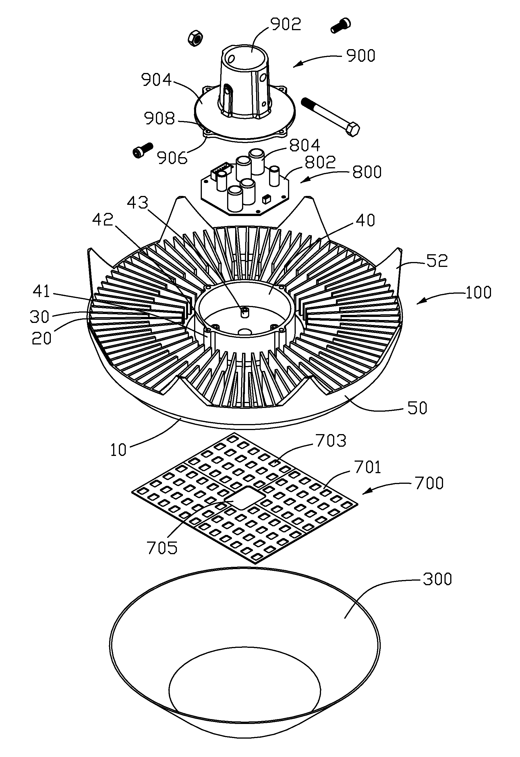
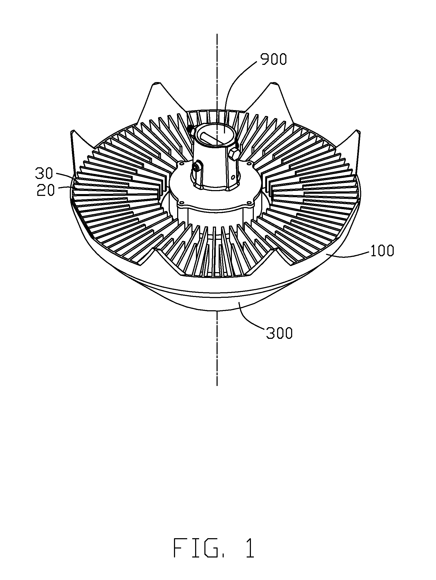
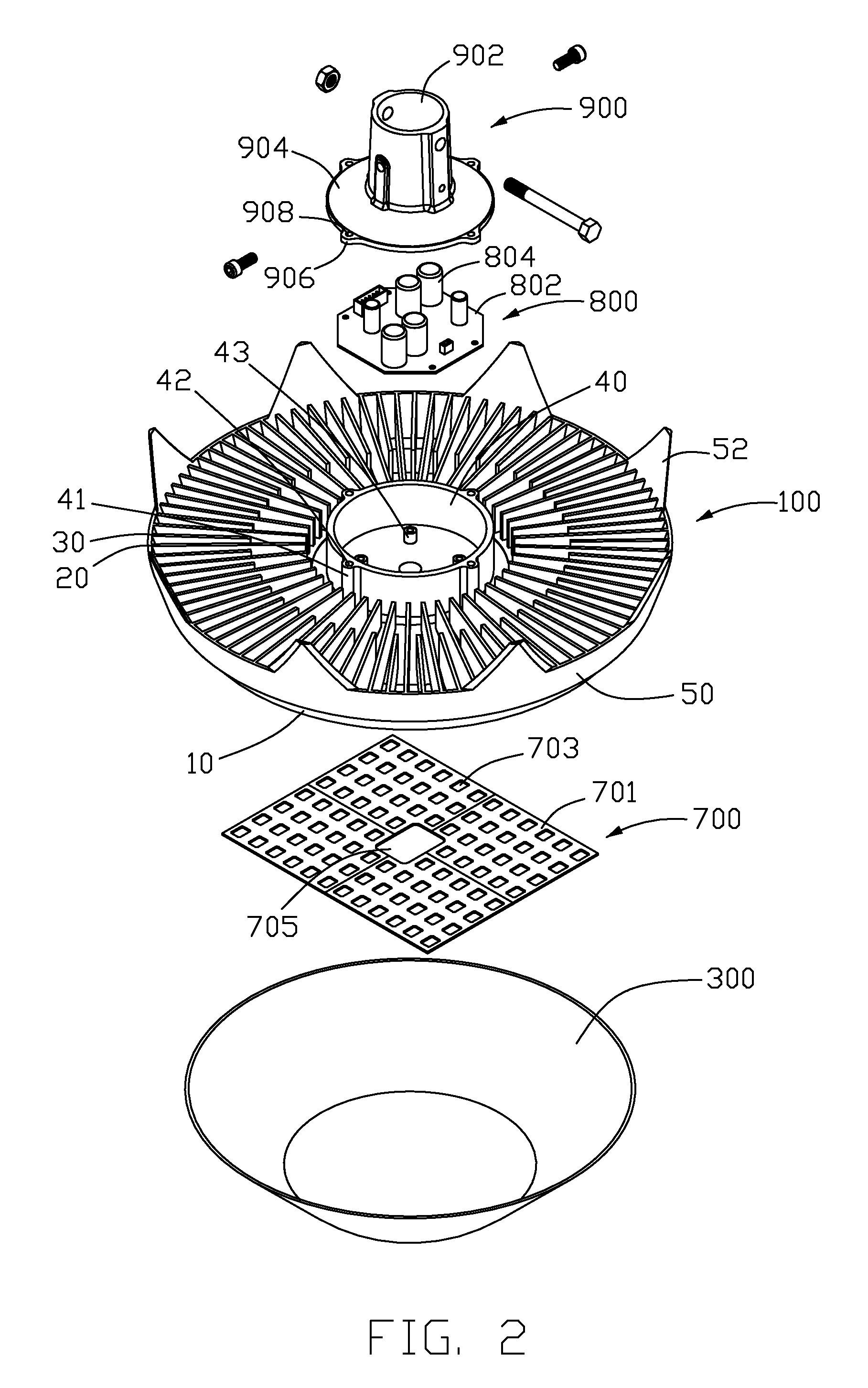
[0014]Referring to FIGS. 1-2, an LED lamp for a lighting purpose comprises an LED module 700, a heat sink 100 for supporting and cooling the LED module 700, and a lampshade 300 mounted below the heat sink 100 for enclosing and protecting the LED module 700. A driving circuit module 800 is received in the heat sink 100 and electrically connected to the LED module 700. A fixture 900 is located above the heat sink 100. The fixture 900 is used for connecting the LED lamp to a supporting structure, such as a supporting post of a lamp stand (not shown).

[0015]The LED module 700 comprises a plurality of LEDs (not shown) mounted on a printed circuit board 701. The LEDs are installed into mounting holes 703 defined in the printed circuit board 701, respectively, and electrically connected to the printed circuit board 701. A through hole 705 is defined in a centre of the printed circuit board 701. The printed circuit board 701 is further electrically connected to the driving circuit module 800...


PUM


Abstract

An LED lamp includes a lampshade, an LED module and a heat sink supporting and cooling the LED module. The heat sink includes a heat absorbing portion having a base plate for mounting the LED module thereon, and engaging with the lampshade for enclosing the LED module. A plurality of fins is formed on a top of the heat absorbing portion, and the fins extend outwardly beyond an outmost edge of the heat absorbing portion. A sidewall connects outmost ends of the fins. A plurality of apertures are defined between the outmost edge of the heat absorbing portion, the fins and the sidewall for allowing an airflow to flow from a bottom to a top of the heat sink via the apertures, thereby to effectively cool the heat sink and accordingly the LED module.

Description

BACKGROUND OF THE INVENTION[0001]1. Field of the Invention[0002]The present invention relates to a light emitting diode (LED) lamp, and more particularly to an LED lamp having a heat sink for improving heat dissipation efficiency of the LED lamp.[0003]2. Description of Related Art[0004]The technology of LED has been rapidly developed in recent years from indicators to illumination applications. With the features of long-term reliability, environment friendliness and low power consumption, the LED is viewed as a promising alternative for future lighting products. LEDs are widely used in many fields such as street lamps. Nevertheless, the rate of heat generation increases with the illumination intensity. This issue has become a challenge for engineers to design the LED illumination, i.e. the LED lamp.[0005]What is needed, therefore, is an LED lamp which has greater heat-transfer and heat dissipation capabilities, whereby the LED lamp can operate normally for a sufficiently long period...

Claims


Application Information

Patent Timeline
Patent Type & Authority Patents(United States)
IPC IPC(8): B60Q1/06
CPCF21V29/004F21V29/75F21V29/89F21V29/773F21Y2101/02Y10S362/80F21Y2115/10
Inventor LIU, YI-SANXIAO, XU-HUAHE, LI
Owner FU ZHUN PRECISION IND SHENZHEN
Why Eureka
Try Eureka