
Wind turbine yawing system, wind turbine and yawing process

a wind turbine and yawing technology, applied in the direction of liquid fuel engines, vessel construction, marine propulsion, etc., can solve the problems of deterioration of gear teeth, insufficient retention capacity of braking systems, and costly repairs, and achieve the effect of greater braking

Inactive Publication Date: 2008-12-02
GAMESA INNOVATION & TECH SA
View PDF2 Cites 28 Cited by
  • Summary
  • Abstract
  • Description
  • Claims
  • Application Information

AI Technical Summary

Benefits of technology

The system provides enhanced braking capacity with reduced space and weight, allowing for easier maintenance and adaptation to varying wind conditions without the need for disassembling the nacelle, thereby improving operational efficiency and reducing repair frequencies.

Problems solved by technology

The problem posed by this process is that once the frame is located in one orientation by means of the motor, it does not remain immobile, but rather gusts of wind can exert a momentum which moves the frame.
Therefore the motor must be constantly running, and the gear teeth of the ring and of the wheel undergo loads in both directions, causing allowances and the deterioration of the gear teeth, which requires costly repairs.
One of them is that the braking systems do not have enough retention capacity against strong gusts of winds.
Increasing the known active braking systems requires a larger friction surface or a greater force for acting on the elements joined to the tower (friction disc or the like), but the weight and space in the upper part of the tower forces making much sturdier towers, increasing the cost of the wind turbine.
Braking by means of drive motors of an acceptable size in the towers themselves is neither enough to prevent movements due to strong gusts of wind.
Another problem is that the elements of the yawing system of the wind turbine, especially the gear ring, the nacelle support ball bearings and the braking systems undergo significant loads, which leads to the frequent need for repairs or replacements.
On the other hand, the gear teeth of the gear ring may undergo wear and tear and / or breakage, and in the known systems, a breakdown in the bearings supporting the nacelle allowing the rotation on the tower, or in the ring where the motor meshes, requires the disassembly of the nacelle, taking it to ground level so as to carry out the repair.

Method used


Image

  • Wind turbine yawing system, wind turbine and yawing process
  • Wind turbine yawing system, wind turbine and yawing process
  • Wind turbine yawing system, wind turbine and yawing process

Examples


Embodiment Construction

[0014]One of the objectives of the invention is to provide a yawing system having elements which can be easily replaced in repair.

[0015]Another objective of the invention is to obtain a braking system with more capacity than the known systems, but which is compact, i.e. it occupies little space in the upper part of the tower.

[0016]Another objective of the invention is to obtain a braking system which can be easily adapted during the assembly to places with different wind conditions.

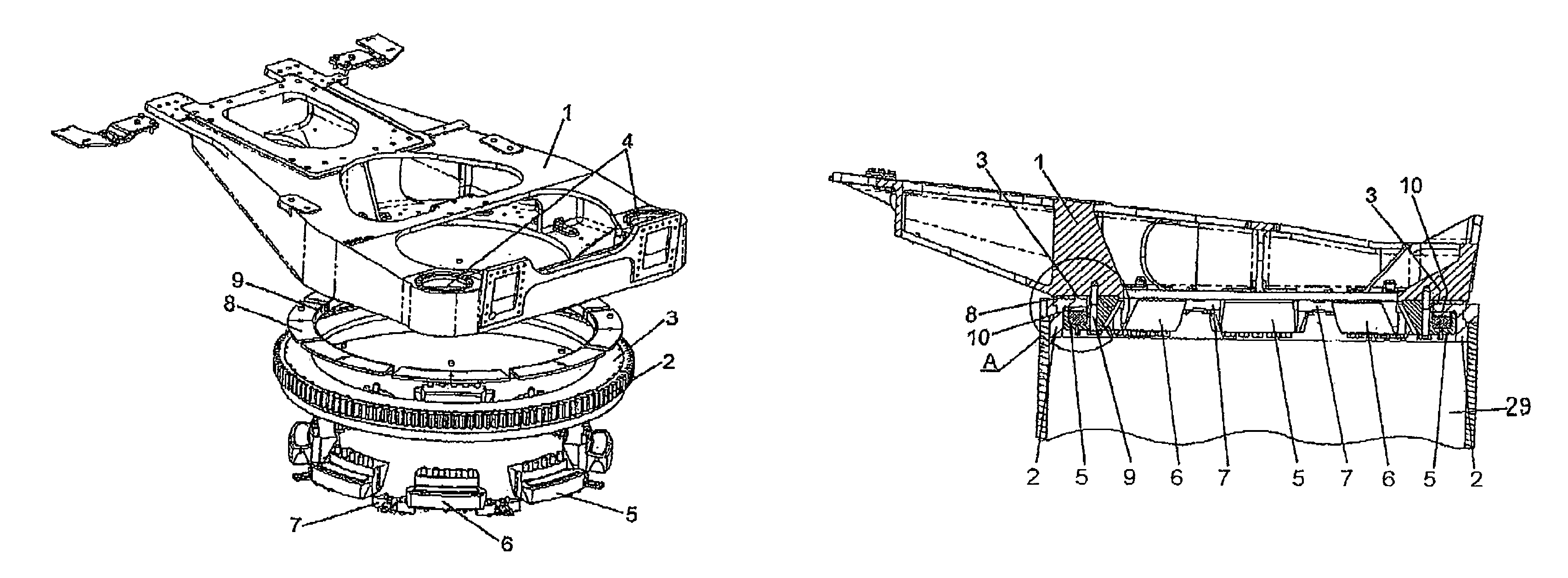
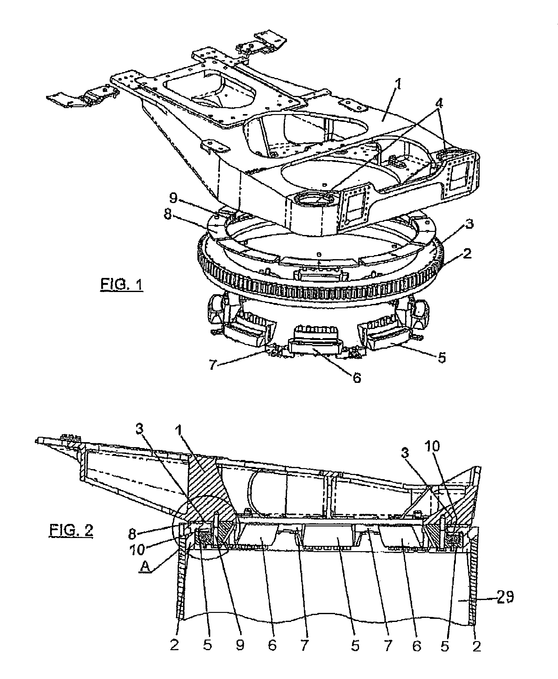
[0017]The yawing system of the wind turbine comprises, as in other known systems, a yawing system joining a tower fixed to the ground with a frame supporting the generator (and forming part of that which is called the nacelle of the wind turbine). This yawing system allows the orientation of the frame with respect to the tower according to the direction of the wind, and comprises at least the following elements:[0018]a gear ring configured to be fixed to said tower, the gear ring having a sliding track on...


PUM


Abstract

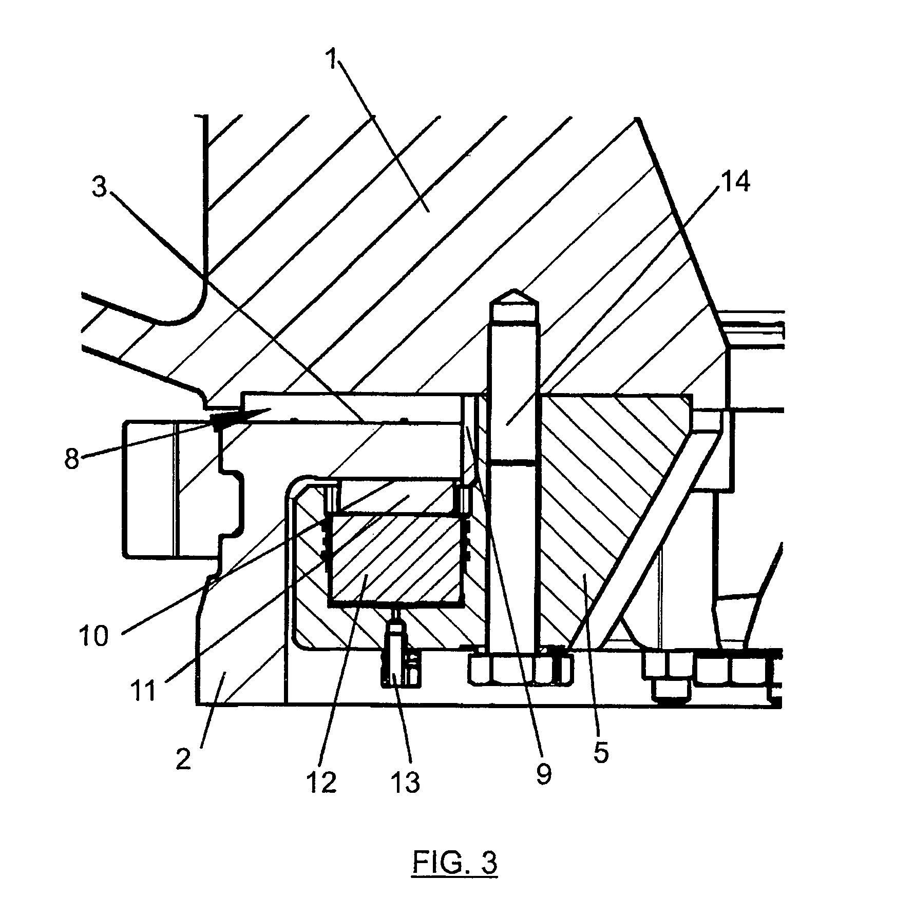
A yawing system for a wind turbine, the wind turbine comprising a tower fixed to the ground and a frame (1) housing an electric power generator, the tower and the frame (1) being joined by the yawing system which allows the orientation of the frame (1) with respect to the tower according to the direction of the wind. The yawing system comprises:a gear ring (2) fixed to the tower, the gear ring having a sliding track (3) on which the frame (1) rests and slides in its yawing movement,at least one geared motor fixed to the frame (1), meshed with the gear ring (2) through a gear wheel,at least one active braking module (5), andat least one passive braking module (6).The invention further comprises a sliding track (3) and a friction track on the gear ring, this friction track (10) being different from the sliding track (3), and the active braking modules (5) and passive braking modules (6) comprising a friction plate (11) acting on the friction track (10) of the ring. The frame (1) rests on the gear ring (2) by means of horizontal plates (8) and radial plates (9) made of a sliding material, and are kept in their position by separating parts (7). Furthermore, the gear ring (2) is divided into gear-toothed circular segments to favor its repair.Other aspects are a wind turbine with the previous yawing system and a yawing process of a turbine by means of the previous yawing system.

Description

FIELD OF THE INVENTION[0001]The invention is encompassed within the field of wind turbine orientation systems, particularly in reference to the means for moving the rotor of the wind turbine to orient it to the wind and to retain it when it is in its objective position, preventing the same wind from moving it.BACKGROUND OF THE INVENTION[0002]Wind turbines consist of a fixed tower which raises an electric generator connected to a rotor by mechanical means above the ground. The rotor is formed by a hub or base joining one or several blades which are responsible for transforming the kinetic energy of the wind into rotational movement of the rotor. The turbine is generally placed on a frame, which is able to move with respect to the tower supporting it such that it allows the rotor to be oriented in the direction of the wind. One manner of orientation can be letting the frame (forming part of what is usually called the nacelle of the wind turbine) freely rotate (leeward orientation), wh...

Claims


Application Information

Patent Timeline
Patent Type & Authority Patents(United States)
IPC IPC(8): F03D7/02
CPCF03D7/0204F03D7/0244F05B2260/902Y02E10/723F16C41/001F16C2360/31Y02E10/72
Inventor LLORENTE GONZALEZ, JOSE IGNACIOGONZALEZ-POSADA MARTINEZ, MIGUEL ANGEL
Owner GAMESA INNOVATION & TECH SA
Learn More