Installation and method for sterilising objects by low-energy electron bombardment

a low-energy electron and sterilising technology, applied in the direction of lavatory sanitory, radiation therapy, therapy, etc., can solve the problems of insufficient optimization, high installation cost, and inability to completely optimize, so as to reduce the space requirement of such an installation.

Inactive Publication Date: 2008-12-02
LINAC TECH
View PDF8 Cites 12 Cited by
  • Summary
  • Abstract
  • Description
  • Claims
  • Application Information

AI Technical Summary

Benefits of technology

[0013]Obviously, the requirement of only one low-energy accelerator / gun-type source leads to a significant reduction in the overall cost as well as a reduced space requirement by comparison with the installations known from the prior art.
[0023]The second mechanical module preferably comprises fourth movement means designed so as to move the object in translation according to axis A″, so as to separate it from said gripping means during its rotation of approximately 90° about this same axis A″, generated by the third movement means. Of course, these fourth means also make it possible to bring the object toward the gripping means, after said rotation has been performed. In this regard, it is noted that the first mechanical module is designed and controlled so that its gripping means re-engage the object having a substantially rectangular parallelepiped shape subjected to the rotation of approximately 90° generated by the third movement means, so that the object can be rotated about axis A′ by the second movement means. Naturally, this second rotation about axis A′ is basically intended to sterilise the two parallel surfaces of the parallelepiped object that were not treated during the first 360° rotation about this same axis. Nevertheless, it can optionally be used to complete the treatment of the other two surfaces already sterilised during the first rotation, but also lighted by the electron beam during the second rotation of the object about said axis A′.
[0026]Preferably, the two inlet and outlet locks in closed position and the treatment chamber jointly form an unsealed, shielded enclosure, which therefore allows for total biological protection from the electron beam, but which is still capable of allowing air to pass through, in particular at the level of the closures of the two locks.
[0027]Each of the two inlet and outlet locks is preferably associated with an elevator oriented in direction Z, which enables the space requirement of such an installation to be reduced considerably. Moreover, each of the two elevators comprises a shielded mobile plate serving as a carrier for the object, which plate is designed so as to ensure the closure of the lock with which it is associated, and therefore constitutes a portion of the unsealed, shielded enclosure mentioned above.

Problems solved by technology

Nevertheless, this installation has a major disadvantage lying in the fact that it requires three distinct low-energy accelerator / gun-type sources in order to perform the sterilisation by irradiation of the entire external surface of each object.
Obviously, this constraint associated with the necessary presence of three complex low-energy sources makes the installation extremely costly, and, therefore, it is not entirely optimised.
Moreover, it is noted that the particularly large space requirement of this installation also constitutes another disadvantage.

Method used


Image

  • Installation and method for sterilising objects by low-energy electron bombardment
  • Installation and method for sterilising objects by low-energy electron bombardment
  • Installation and method for sterilising objects by low-energy electron bombardment

Examples


Embodiment Construction

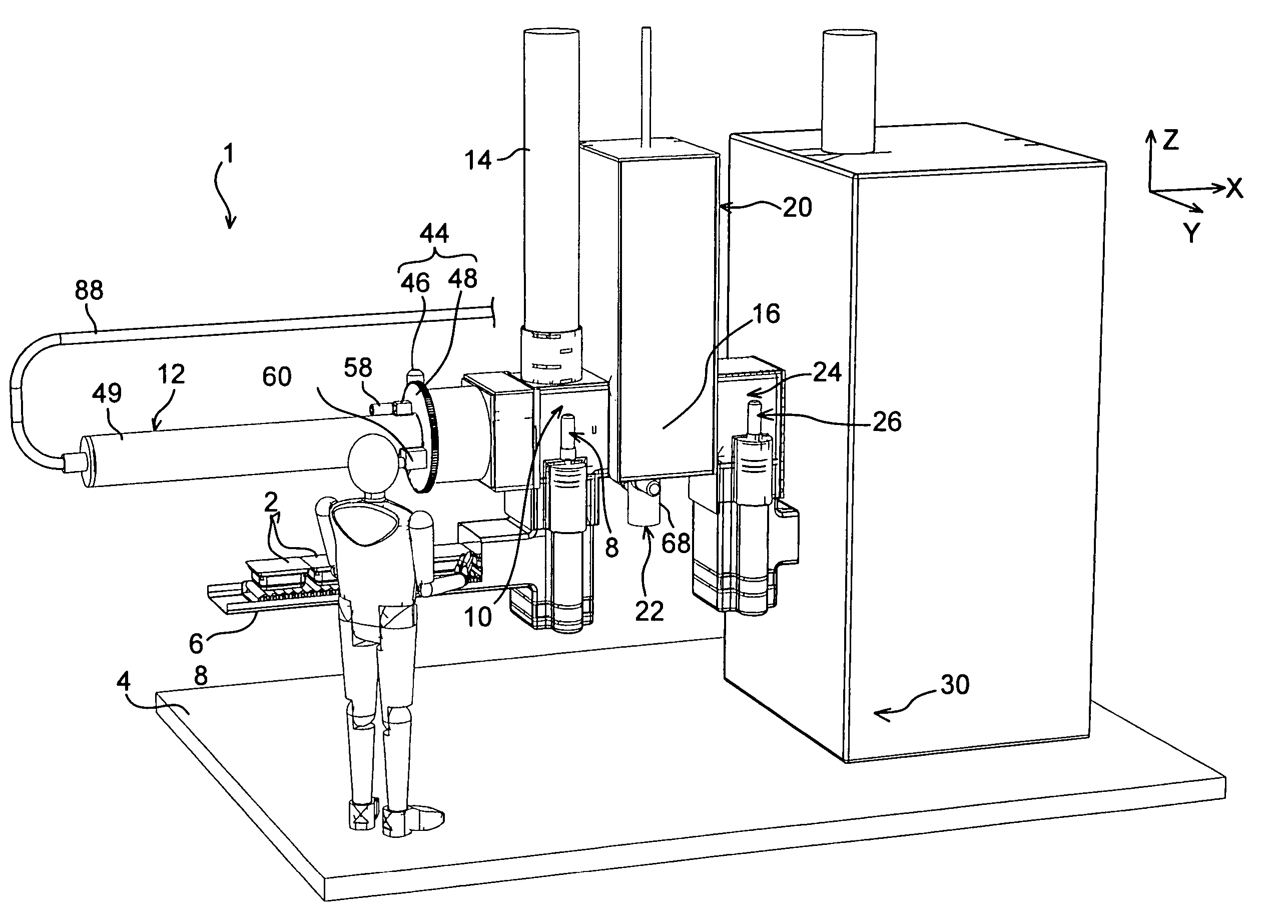
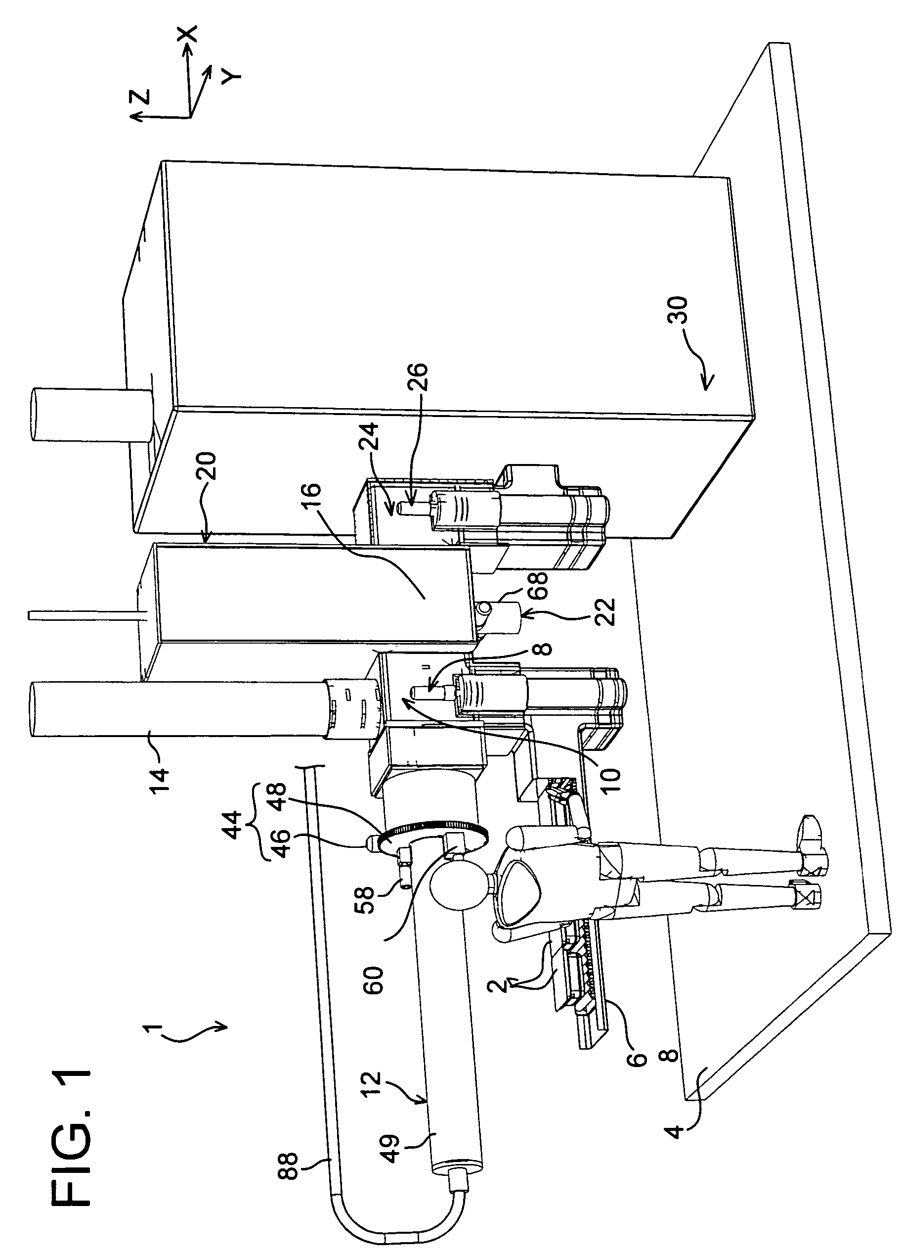
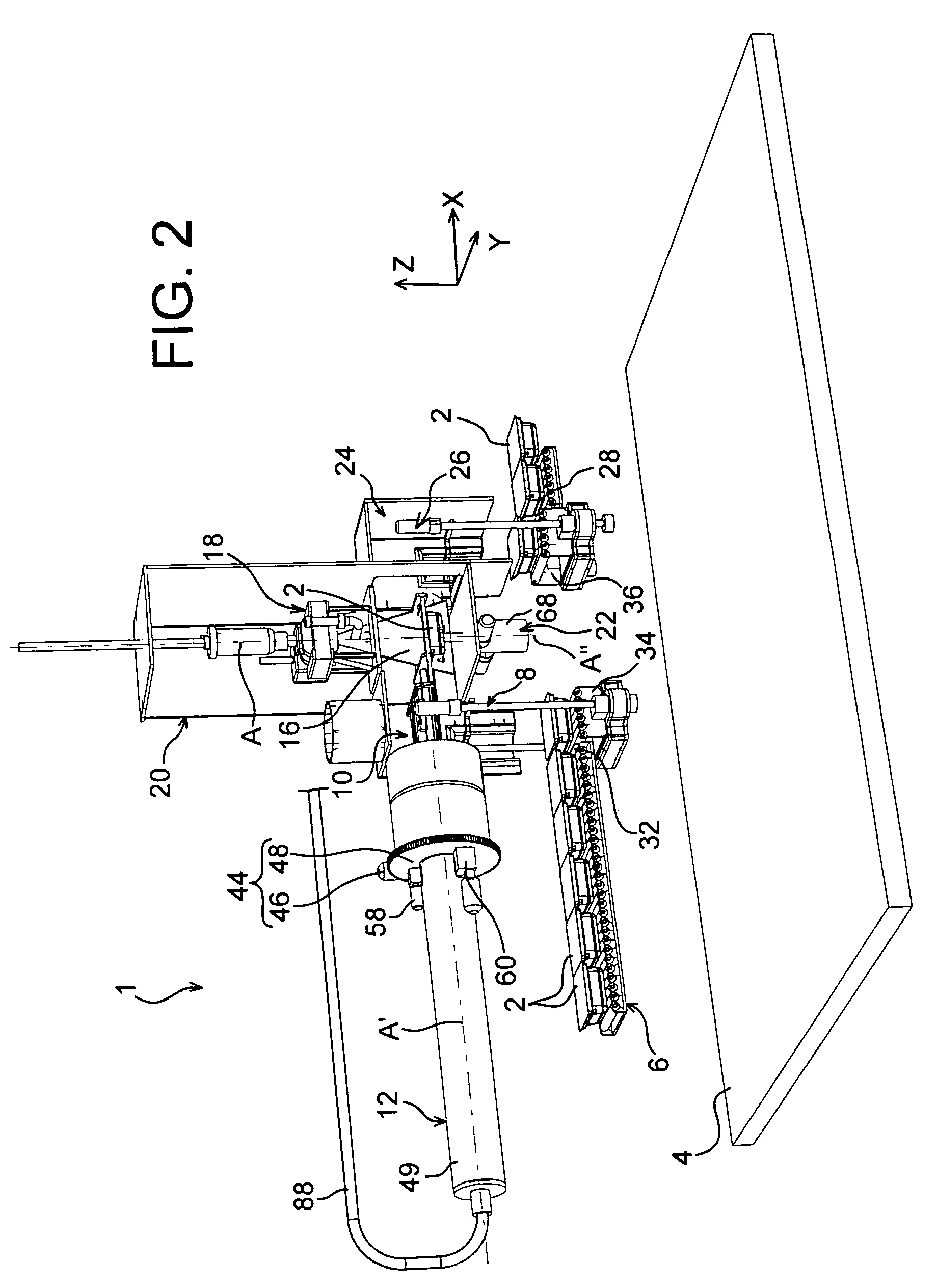
[0040]In reference first to both FIGS. 1 and 2, an installation 1 for sterilising objects 2 by low-energy electron bombardment can be seen, which installation 1 is intended in particular for treating objects having a substantially rectangular parallelepiped shape.

[0041]As mentioned above, this shape corresponds in particular to that of tubs containing a multitude of elements, for example, one hundred per tub, which elements are preferably chemically pre-sterilised, such as medical syringes.

[0042]The installation 1 is placed on a floor 4, which can be characterised as a horizontal plane. It can thus be noted that the description will be provided in reference to a direction X parallel to the ground 4 and corresponding to a direction of forward movement of the objects in the installation, a direction Y corresponding to a transverse direction of the installation also parallel to the ground 4, as well as a direction Z corresponding to a direction of the height which is orthogonal to said...


PUM

PropertyMeasurementUnit
thicknessaaaaaaaaaa
vertical distanceaaaaaaaaaa

Abstract

The invention relates to an installation (1) for sterilising objects (2) by low-energy electron bombardment, including sterilisation means (18) capable of generating an electron beam along an axis (A) passing through a treatment chamber (16). According to the invention, the installation includes a mechanical module (12) designed so as to be capable of generating a relative rotation movement, between the object and the sterilisation means, about an axis (A′) chosen so that axis (A) of the electron beam generated by the sterilisation means continuously passes through the external surface of the object during the relative rotation movement about the axis (A′). In addition, it comprises mechanical module (22) enabling the object to be rotated about an axis (A″) oriented orthogonally with respect to axis (A′).

Description

TECHNICAL FIELD[0001]This invention relates in general to the field of sterilising objects by low-energy electron bombardment on the external surface of said objects.[0002]It applies particularly but not exclusively to sterilisation by low-energy electron bombardment of objects having a substantially rectangular parallelepiped shape, such as objects called “tubs” corresponding to closed containers containing a multitude of elements that are preferably chemically pre-sterilised, such as medical syringes.[0003]More specifically, the invention relates to an installation for sterilising objects by low-energy electron bombardment on the surface of said objects, as well as a sterilisation method capable of being implemented by such an installation.PRIOR ART[0004]The prior art includes installations for sterilising objects with a substantially rectangular parallelepiped shape by low-energy electron bombardment, i.e. with an energy lower than around 400 KeV.[0005]To do this, these installat...

Claims


Application Information

Patent Timeline
Patent Type & Authority Patents(United States)
IPC IPC(8): A61N5/00A61L2/00H01J37/20
CPCA61L2/087A61L2202/122A61L2202/24
Inventor FONTCUBERTA, PHILIPPEMORISSEAU, DIDIERCOUPEZ, ARNAUD
Owner LINAC TECH
Why Eureka
Try Eureka