
Device, method, computer program product, and carrier for indicating at least one of an orbit of, and a deviation from a nominally round surface

a technology of mechanical objects and orbits, applied in the direction of mechanical counters/curvatures, programme control, instruments, etc., can solve the problem of not being labor-intensive to operate, and achieve the effect of facilitating the change or setting up of the frequency map

Inactive Publication Date: 2008-12-09
AB SKF
View PDF17 Cites 9 Cited by
  • Summary
  • Abstract
  • Description
  • Claims
  • Application Information

AI Technical Summary

Benefits of technology

Enables efficient, non-labor-intensive measurement of mechanical object surfaces, providing insights into roundness, orbit, and quality, even in challenging environments, with cost-effective components and flexibility in measurement angles, suitable for various manufacturing processes.

Problems solved by technology

Further, its operation is not labor-intensive.

Method used


Image

  • Device, method, computer program product, and carrier for indicating at least one of an orbit of, and a deviation from a nominally round surface
  • Device, method, computer program product, and carrier for indicating at least one of an orbit of, and a deviation from a nominally round surface
  • Device, method, computer program product, and carrier for indicating at least one of an orbit of, and a deviation from a nominally round surface

Examples


second embodiment

[0090]Now a system of simultaneous equations will be derived. The fact that the derivation of the formula is done using three distance gauges in relation to a mechanical object can be seen as an attempt to simplify the derivation in order to increase its understanding. In this preferred embodiment, the processor is configured for generating the deviation profile, R, based on the following expression,

AR=G, where[0091]A is a matrix based on the distance measuring angles,[0092]R is a vector comprising the deviation profile, and[0093]G is a matrix comprising the distances data sets.

[0094]The vector R comprises stacked data concerning the deviation from a nominally round surface and the orbit in two dimensions of the mechanical object. There is an alternative representation of R in the form of a matrix that will be used below.

[0095]Considering a nominally round object with some small form imperfections, such as a ring or roller of a rolling element bearing. The example concerns external ...

third embodiment

[0105]Now indicating at least one of an orbit of, and a deviation from a nominally round surface of a mechanical object will be derived. The fact that the derivation of the formula is done using three distance gauges in relation to a mechanical object can be seen as an attempt to simplify the derivation in order to increase its understanding. In a preferred embodiment, the processor is configured for generating the deviation profile, R, based on the following expression, in the case the distance data sets comprise three distances:

kr=R, where

where r is a vector comprising ri being the distance read by distance gauge i (i=1 . . . 3) and k is a vector comprising weights ki (i=1 . . . 3).

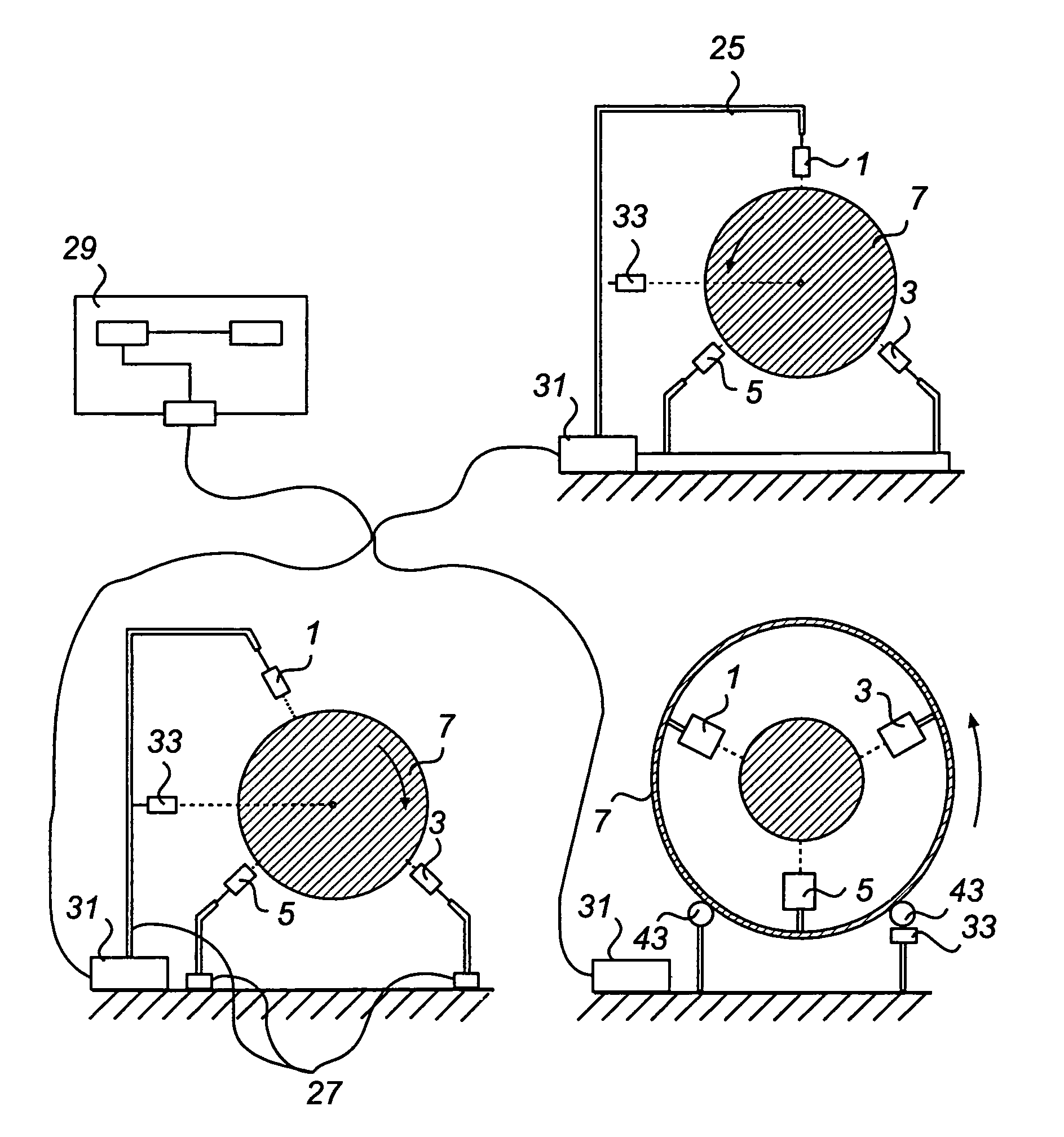
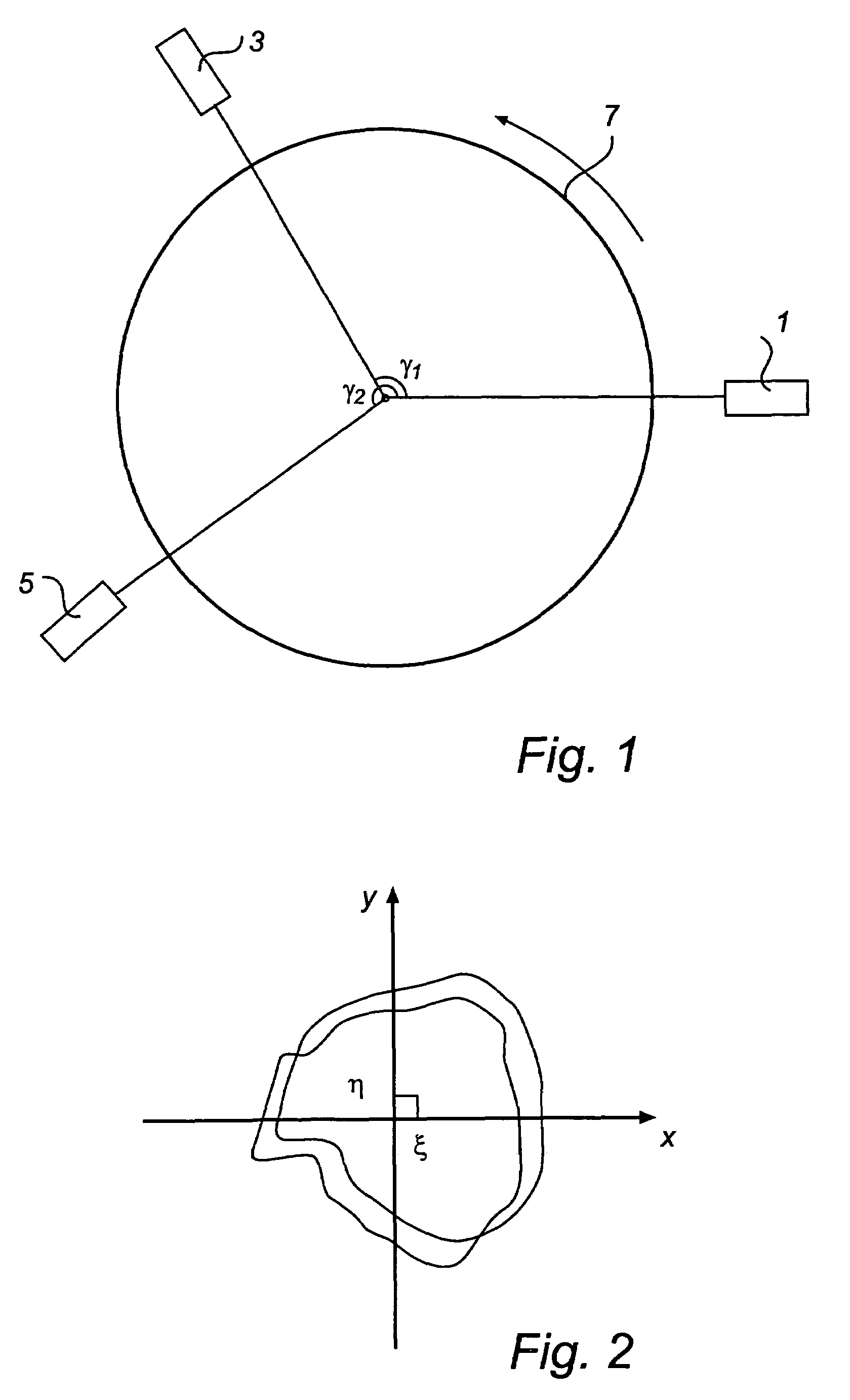
[0106]Now referring back to FIG. 1 again, a mechanical object with three distance gauges 1, 3, 5 is presented. Using the three distance gauges 1, 3, 5, the operation of which at least presenting a distance component in radial direction, it is possible to form an invariant of the following linear combina...


PUM


Abstract

A device is provided for measuring roundness of a mechanical object even if the mechanical object performs an orbit movement. The orbital movement and the surface roundness are separated. It is even possible to divide the orbital movement into an x component and a y component. The measurement is accomplished in a single measurement. After measuring it is possible to decide what to indicate: the orbit of the mechanical object, the deviation from a nominally round surface, or the combination of both. This is possible since once the data has been obtained it is then possible to use the data once or a number of times to indicate the orbit of the mechanical object, the deviation from a nominally round surface, or the combination of both.

Description

FIELD OF THE INVENTION[0001]The present invention relates to a device, method and computer program product for indicating at least one of an orbit of, and a deviation from a nominally round surface of a mechanical object.[0002]It also relates to a device and method for indicating the quality of a nominally round surface. The invention also relates to a carrier comprising the computer program product and to a storage means comprising distance data usable for the device indicating an orbit of or deviation from a nominally round surface of an object as well as a device for measuring distance data sets being used as input to the device.BACKGROUND OF INVENTION[0003]In U.S. Pat. No. 5,077,908, an apparatus for measuring the roundness of a surface of an object is disclosed. The apparatus comprises a bifurcated head rotatably mounted upon a spring loaded arm. The head has two edge plates which can be brought into tangential contact with the periphery of a rotating object. When the head is b...

Claims


Application Information

Patent Timeline
Patent Type & Authority Patents(United States)
IPC IPC(8): G01B21/20
CPCG01B21/30G05B19/4065G05B2219/37258G05B2219/37339
Inventor BANKESTROM, JAN-OLOFGABRIELSSON, GORANGOTHBERG, ANDERS
Owner AB SKF
Learn More