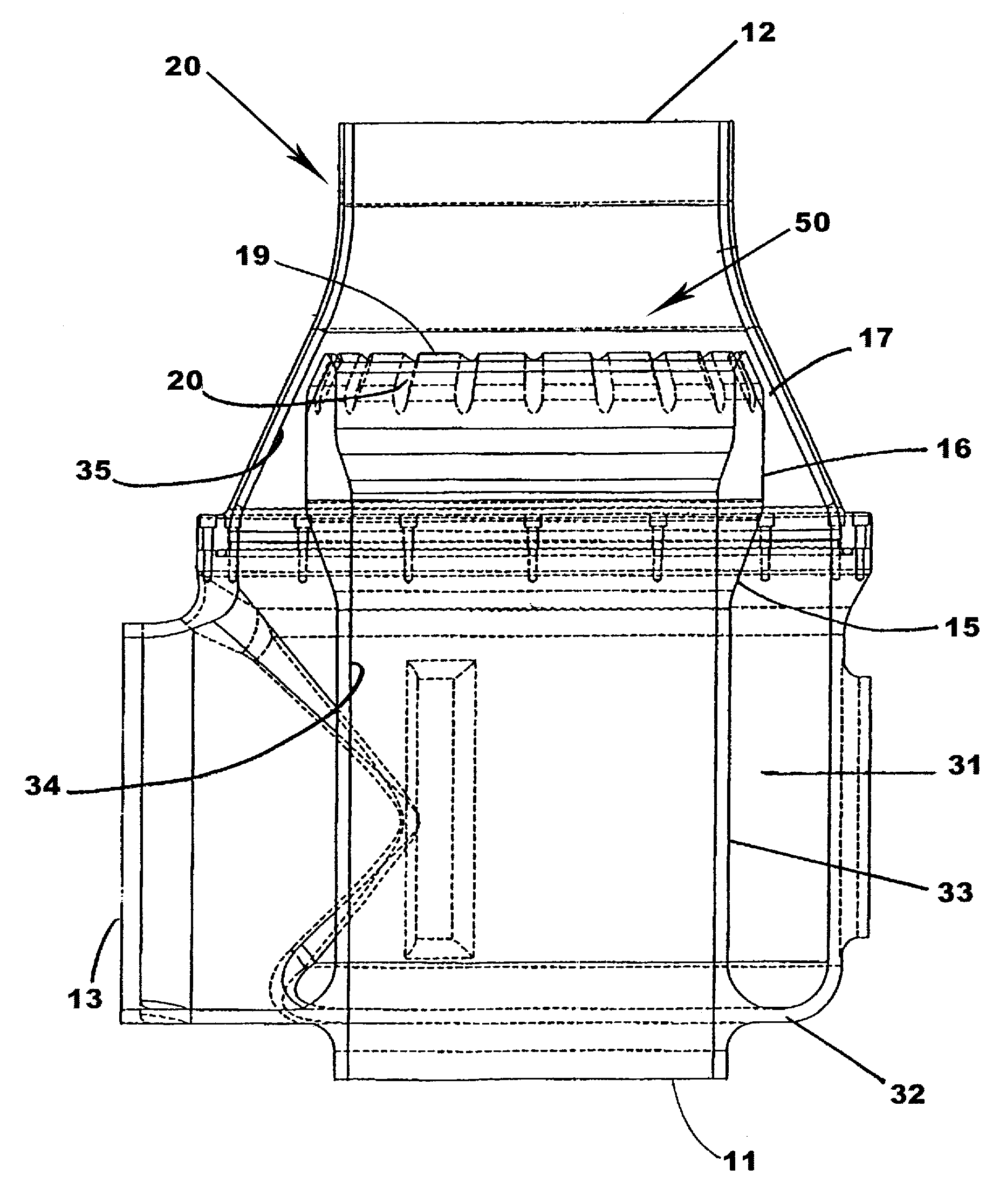
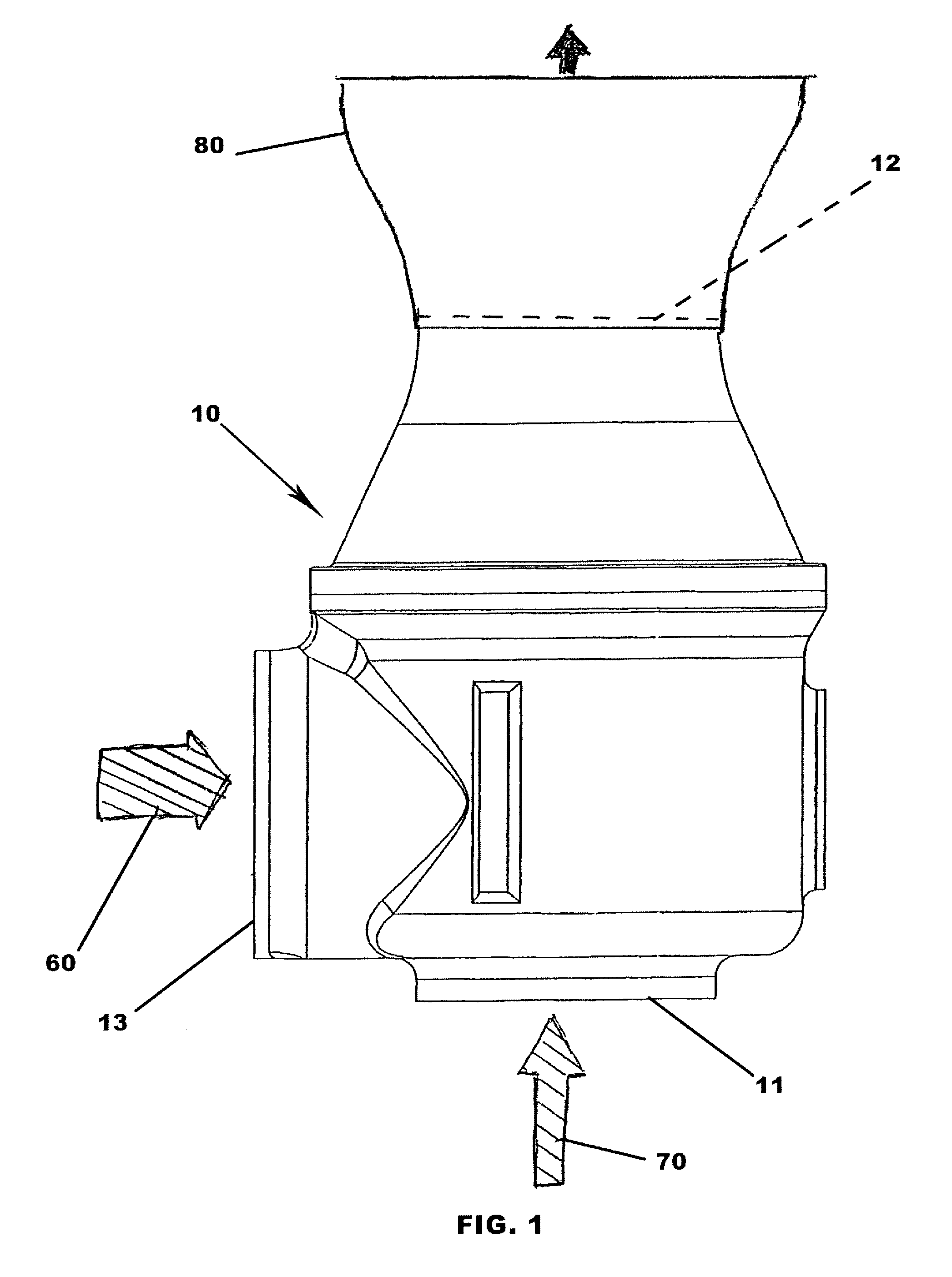
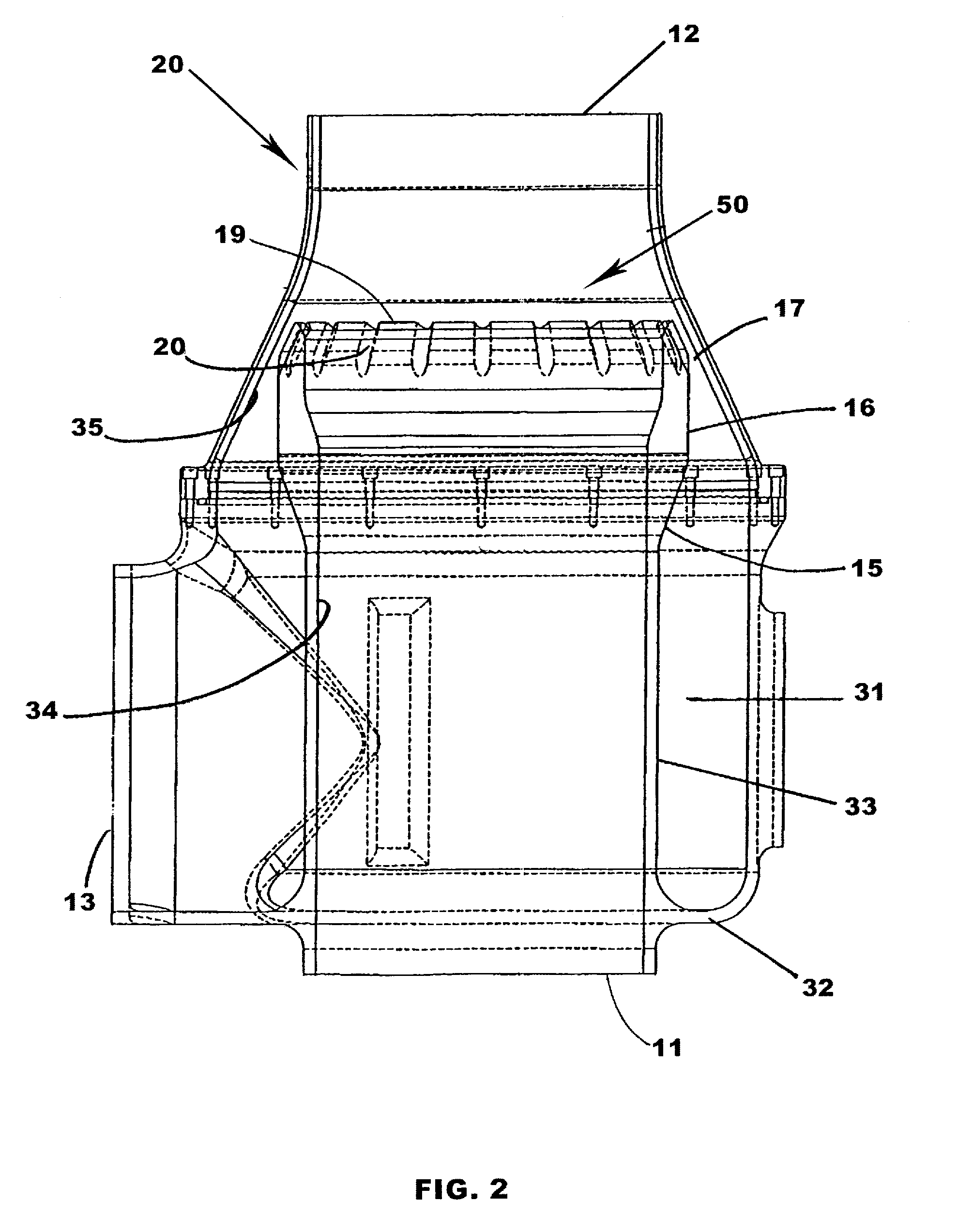
Fish pump

a technology for fish and pump, applied in the field of fish pumps, can solve the problems of fish present a particular problem, severe damage to fish, injury or death of fish, etc., and achieve the effect of inhibiting damage to the product passing through the pump

Active Publication Date: 2008-12-09
LINDGREN PETER B
View PDF3 Cites 18 Cited by
  • Summary
  • Abstract
  • Description
  • Claims
  • Application Information

AI Technical Summary

Benefits of technology

[0019]The present invention is directed toward an improved Coanda effect pump for transporting liquid and associated product by induced flow. The pump has a housing with a primary intake for primary flow, a secondary intake for induced flow, an internal pump chamber for intermixing said primary flow and said secondary flow, and an outlet for discharge. The primary intake and said secondary intake are constructed and arranged so as to terminate in a orifice within the housing. The orifice allows the primary flow to be circumferential with the induced flow with both primary flow and induced flow exiting said orifice into a pump chamber. The orifice includes a circumferential gap between the primary intake and the housing directing the primary flow into the pump chamber at an acute angle to the axis of the induced flow. The secondary intake has an internal surface and an external surface with the orifice having flutes formed in the external surface of the secondary intake. An enlarged mouth extends a distance within the internal surface of said secondary intake. The mouth has a constant diameter for forming the secondary flow whereby the primary flow and the secondary flow intermix in the pump chamber with minimal swirl to inhibit damage to the product passing through the pump.
[0020]Therefore, it is an objective of this invention to provide a Coanda effect pump which creates a high speed boundary layer with a means for then breaking up the boundary layer to increase the efficiency of intermixing of the primary flow and the induced flow.
[0021]Still another objective of the invention is to teach the use of orifice serration and a discharge nozzle, wherein Coanda pumps with small gaps can be configured to have higher efficiencies than large gaps, allowing very high induced flows from a primary pump at low flows.

Problems solved by technology

Fish present a particular problem due to their strength yet fragile structure.
For instance, in commercial fishing the use of a fishing net to pull fish into a boat can result in injury or death to the fish.
Current fish pumps have limited size capacity and transporting larger fish can result in severe damage to the fish.
Unfortunately even when the current fish pumps are used within a capacity range, the pump designs can lead to excessive stress upon the fish due to wall impact where pressurized water meets the fish laden water.
If the fish is injured, a loss of blood can occur which not only affects the well being of the fish but if the fish is about to be harvested, the blood loss has a direct correlation on the amount of income obtained in a sale of the fish since fisherman are paid by the pound and the loss of blood is a loss of weight.
The problem with such conventional pumps is the sudden turbulence or swirl due to the differential energy in the circumferential primary flow and the inner column of induced flow.
Large active fish can be severely injured at this junction wherein scales and fins can be torn off or side wall impact so severe that the fish can killed.
When the fish enters tail first, it can do little to prevent impacting of the walls of the pump as it passes through.
Also, when the fish encounters the water swirl formed at the point of water mixing, the forward motion through the pump with deceleration then acceleration results in the likely impact against the wall of the pump.
For that reason, a fish traveling from the first segment would impact with the converging Coanda surface, thereby causing fish damage or fish kill.
Still another known problem of the prior art Coanda effect pumps was created by the divergence of the second segment from the minimum throat diameter at the Coanda surface to the downstream end of the second segment.
This divergence created a larger cross section in the second segment downstream of the Coanda surface and would not permit the effective transfer of the primary fluid momentum throughout the entire cross section of the second segment.
Such a core resulted in unnecessary turbulence and loss of efficiency.
Yet a further problem with the previous pump related to the liquid injection through the Coanda orifice from the plenum which contained the primary liquid used for injection through the orifice.
This decreased the Coanda effect and, hence, the efficiency of the pump.
Another problem addressed by the patent was excessive turbulence in the boundary layer between the primary flow and the secondary column.
However, the reduction of the transition area increases the turbulence and acceleration.
Although larger sizes are disclosed as possible, the loss of water uniformity occurs at the Coanda surface and fish over 8 inches in diameter as again subjected to injury or death.
To increase the size of the reciprocating or centrifugal pump is very expensive and the effects of the greater pressures and velocities of the liquid, in the Coanda effect pump, may cause more trauma to the product.
The '946 pump is limited in efficiency to pump diameters of 8 inches or less.
When high winds or a storm occurs, wave action can result in a breach of the structure leading to a loss of fish.
However, feeding of the fish becomes difficult since feeding must now address the body of water above the cage which may include a current.
However, typical food for farm fish is in a pellet form which is damaged by most pumps.
Damaging of the fish pellets results in smaller size matter which may not be detected by the fish before floating away.

Method used


Image

  • Fish pump
  • Fish pump
  • Fish pump

Examples


example 1

[0043]A pump of the prior art having a gap injection angle of 43 degrees and 0.4 inches has a flow ratio of 0.362. The addition of a discharge nozzle increase the flow ratio to 0.4.

[0044]If the gap injection angle of 43 degrees is maintained but the gap reduced to 0.3 inches, the efficiency allows a flow ratio of 0.508. The addition of the discharge orifice of this invention increases the flow ratio to 0.532. If the flutes are present on the orifice, but no discharge nozzle, the efficiency is raised from 0.508 to 0.528. If the discharge nozzle is included with the orifice flutes, then the efficiency is raised from 0.508 to 0.543.

[0045]If the gap injection angle of 43 degrees is maintained but the gap angle reduced to 0.2 inches, the efficiency allows a flow ratio of 0.560. The addition of a discharge orifice increases the flow ratio to 0.600. If the flutes are present on the orifice, but no discharge nozzle, the flow ratio is raised from 0.560 to 0.570. If the discharge nozzle is in...

example 2

[0046]A pump of the prior art having a gap injection angle of 35 degrees and 0.4 inches has a flow ratio of 0.440. The addition of a discharge orifice increases the flow ratio to 0.470.

[0047]If the gap injection angle of 35 degrees is maintained but the gap angle reduced to 0.2 inches, the efficiency allows a flow ratio of 0.592. The addition of a discharge orifice increases the flow ratio to 0.622. If the flutes are present on the orifice, but no discharge nozzle, the flow ratio is raised from 0.592 to 0.623. If the discharge nozzle is included with the orifice flutes, then the flow ratio is raised from 0.592 to 0.640.

example 3

[0048]A pump of the prior art having a gap injection angle of 25 degrees and 0.4 inches has a flow ratio of 0.457. The addition of a discharge orifice increases the flow ratio to 0.471.

[0049]If the gap injection angle of 25 degrees is maintained but the gap angle reduced to 0.2 inches, the efficiency allows a flow ratio of 0.651. The addition of a discharge nozzle increases the flow ratio to 0.674. If the flutes are present on the orifice, but no discharge nozzle, the flow ratio is raised from 0.651 to 0.707. If the discharge nozzle is included with the orifice flutes, then the flow ratio is raised from 0.651 to 0.739.

[0050]The test performed evidences that the prior art pump having a 43 degree angle and 0.4 inch gap can have the flow ratio increased from 0.362 to 0.739 by use of a 25 degree angle with a 0.2 inch gap wherein the orifice is fluted and a discharge nozzle is added to the pump. Coanda pumps with small gaps can be configured to have higher efficiencies than with large ga...


PUM


Abstract

An improved liquid pump for transporting live fish or other products in an induced flow has secondary line with one end to be placed in a pool of liquid containing fish or other products. The other end of the line is connected to a housing having an internal pump chamber. A primary intake has one end connected to a reservoir of liquid and the other end connected to the housing concentrically about the secondary line. As liquid flows through the primary intake into the pump chamber and out the outlet, the Coanda effect results in a low pressure area in the pump chamber. The liquid in the secondary line is induced to fill the low pressure area. By shaping and directing the primary intake and the secondary intake within the pump chamber a more efficient pump is produced.

Description

FIELD OF THE INVENTION[0001]This invention relates to the fishing industry and, more particularly, to fish pumps capable of moving a liquid containing fish or other fragile organisms.BACKGROUND OF THE INVENTION[0002]In the fishing industry, including the aquaculture industry, and the food industry, as a whole, a primary objective is to move large numbers of products without damage from the source to the marketplace. Fish present a particular problem due to their strength yet fragile structure. The movement of fish, whether from fish nets or retention areas, is most desirable if the fish is not injured during the transfer.[0003]For instance, in commercial fishing the use of a fishing net to pull fish into a boat can result in injury or death to the fish. If the fish are transferred directly from the fishing net into a holding tank on the fishing boat by use of a fish pump, the fish can be transferred without injury thereby delaying the processing time. Current fish pumps have limited...

Claims


Application Information

Patent Timeline
Patent Type & Authority Patents(United States)
IPC IPC(8): F04F5/00A01K61/00A01K63/00A01K79/00
CPCA01K61/007A01K79/00A01K61/60F04F5/00F04F5/10F04F5/46Y02A40/81A01K61/80
Inventor LINDGREN, PETER B.
Owner LINDGREN PETER B
Why Eureka
Try Eureka