Modular tower structure

Active Publication Date: 2008-12-16
TOWER SOLUTIONS
View PDF23 Cites 30 Cited by
  • Summary
  • Abstract
  • Description
  • Claims
  • Application Information

AI Technical Summary

Benefits of technology

[0043]The invention, thus, provides an improved attachment, preferably, of unitary construction for retaining aforesaid accessories. It provides an improved metal fitting which offers a

Problems solved by technology

Such structures are heavy and take a relatively long time to erect, repair and the like.
Replacement in whole, or in part, can take significant amounts of time.
In an emergency, when a plurality of such towers are struc

Method used


Image

  • Modular tower structure
  • Modular tower structure
  • Modular tower structure

Examples


Embodiment Construction

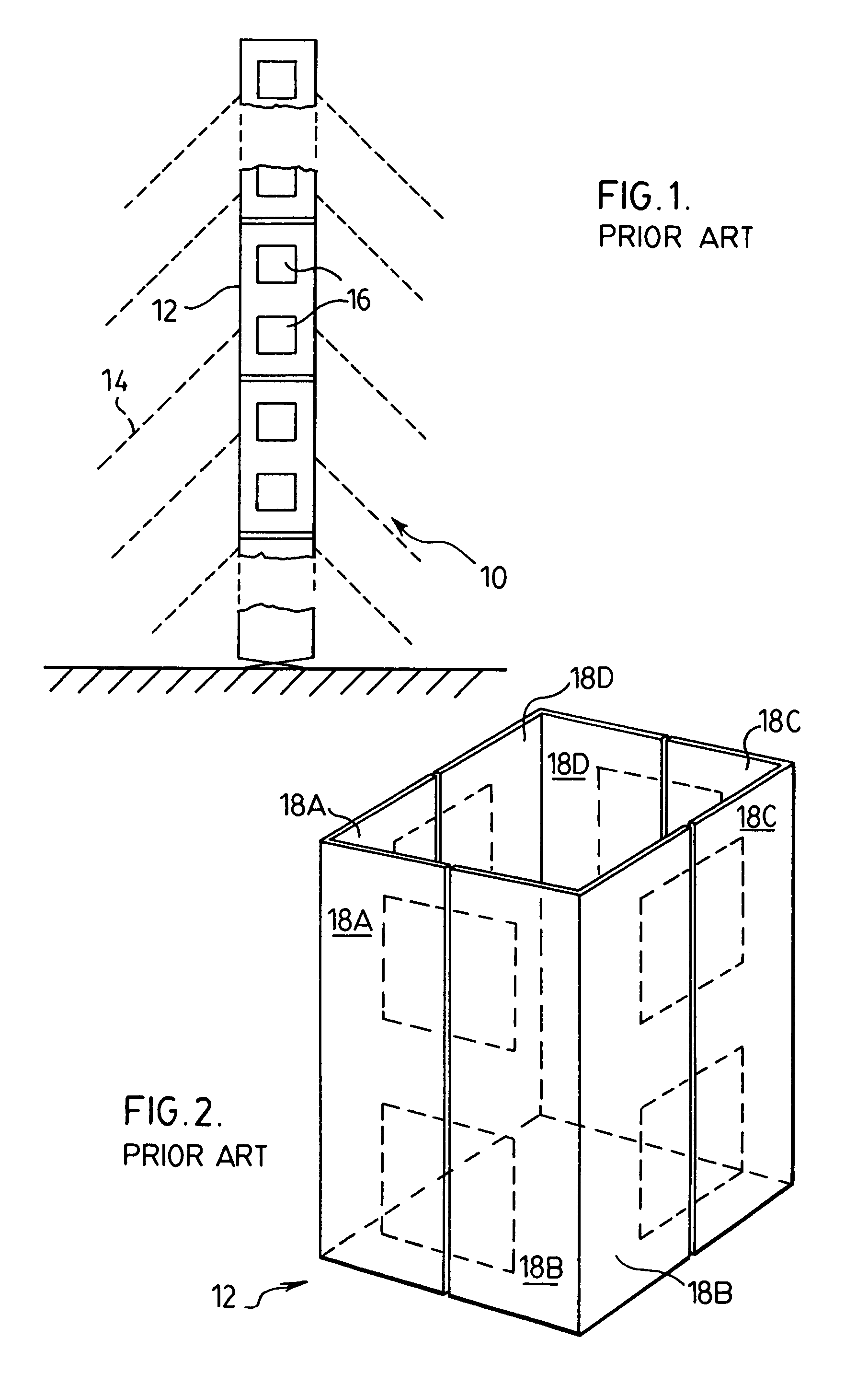
[0056]With reference to FIG. 1, this shows generally as 10 a tower formed of a plurality of aluminum modular units 12 shown in more detail with reference to FIG. 2.

[0057]The tower may have at least two and preferably ten modules bolted together to a desired height and is retained by guy ropes 14 to the ground by fittings (not shown). Each module 12 has a plurality of apertures 16 on each of its four sides.

[0058]With reference to FIG. 2, prior to welding assembly module 12 to another module 12 during construction of tower 10, each module 12 is constructed from four identical angled panels, having sides 18A, 18B, 18C and 18D, by welding to form an essentially rectangular box of equal width and breadth but of a longer length (height). Apertures 16 shown in ghost lines are subsequently cut out of each of the panel sides 18A-18D. Typically, this prior art module 12 has a width and breadth of 41 cm and a length of height 2.0-2.5 m.

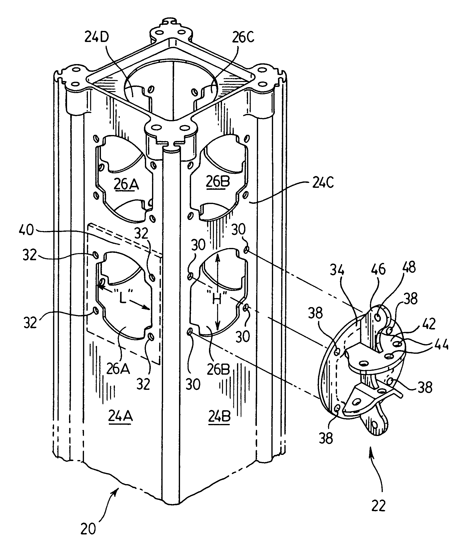
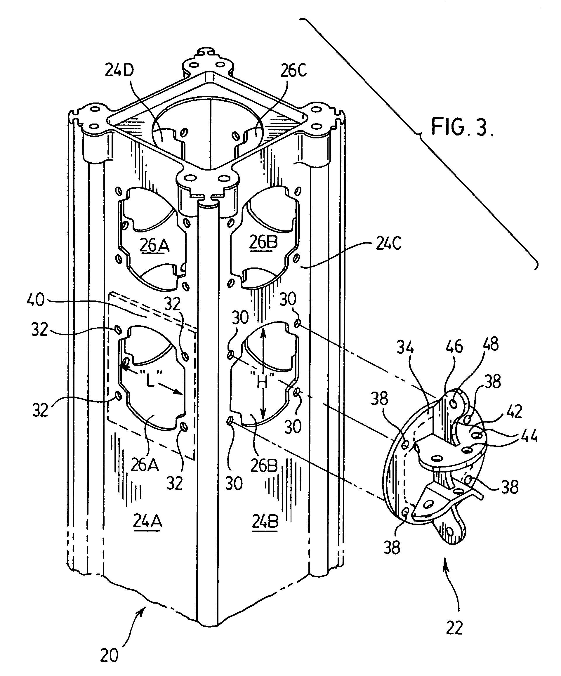
[0059]FIG. 3 shows generally as 20 an aluminum rectangular...


PUM


Abstract

A fitting is provided for use in retaining a plurality of accessory members to a vertical modular structural unit of a telecommunications tower or electricity pylon. The unit has a plurality of vertical sides wherein each side has at least one side aperture. The fitting has a body; a body plate attached to the body and so-shaped as to be cooperable with a side of the unit and receivable in intimate engagement within the side aperture; attachments by which the fitting is attachable to the structure and the body plate is retained thereto receivable within the side aperture by retaining bolts; the body having at least one accessory, such as a guy rope, insulator, dish and platform-receiving aperture for retaining the accessory to the body. The shape of the apertures in each unit side which is complimentary with the body plate, provides a lighter, stronger and more efficacious modular unit and tower.

Description

FIELD OF THE INVENTION[0001]This invention relates to fittings connectable to modular units for use in telecommunication towers, electricity pylons, and like structures; said modular units; and said structures.BACKGROUND OF THE INVENTION[0002]Conventional towers, pylons, and the like, for carrying cables for electrical transmission across the country have, typically, splayed or parallel legs with relatively large footprints and have connecting cross-members, formed of steel members. Such structures are heavy and take a relatively long time to erect, repair and the like. Replacement in whole, or in part, can take significant amounts of time. In an emergency, when a plurality of such towers are structurally damaged or the cables thereon snapped by the effect of ice build-up due to, e.g. freezing rain, this can cause very serious disruption to the transmission of electricity, throughout a community or larger area.[0003]Recently, alternative tower structures have been introduced as temp...

Claims


Application Information

Patent Timeline
IPC IPC(8): E04H12/00E04H12/08E04H12/18E04H12/20E04H12/24H01Q1/12H02G3/04H02G7/20
CPCE04H12/08E04H12/185E04H12/20E04H12/24H01Q1/1207H01Q1/1242H02G3/0493H02G7/20
Inventor RIOUX, ANDRE
Owner TOWER SOLUTIONS
Why Eureka
Try Eureka