Inkjet printhead with inlet priming feature

a technology of inlet priming and inkjet printers, which is applied in printing and other directions, can solve the problems of complicated distribution of ink through micron-scale conduits to individual mems nozzles in inkjet printheads, and achieve the effects of reducing the co-efficient of static friction, and reducing the friction between particles

Active Publication Date: 2008-12-16
SILVERBROOK RES PTY LTD +1
View PDF22 Cites 26 Cited by
  • Summary
  • Abstract
  • Description
  • Claims
  • Application Information

AI Technical Summary

Benefits of technology

[0021]A planar thermal actuator, with contacts directly deposited onto the CMOS electrodes and suspended heater element, avoids hotspots caused by vertical or inclined surfaces so that the contacts can be much smaller structures without acceptable increases in resistive losses. Low resistive losses preserves the efficient operation of a suspended heater element and the small contact size is convenient for close nozzle packing on the printhead.
[0385]Optionally, the nozzle plate has an exterior surface with formations for reducing its co-efficient of static friction (known as ‘stiction’).

Problems solved by technology

Distributing ink through micron-scale conduits to individual MEMS nozzles in an inkjet printhead is complicated by factors that do not arise in macro-scale flow.
This can be useful in printheads, such as bleed holes that vent trapped air bubbles but retain the ink, but it can also be problematic if stops ink flow to some chambers.

Method used


Image

  • Inkjet printhead with inlet priming feature
  • Inkjet printhead with inlet priming feature
  • Inkjet printhead with inlet priming feature

Examples


Embodiment Construction

[0443]In the description than follows, corresponding reference numerals relate to corresponding parts. For convenience, the features indicated by each reference numeral are listed below.

[0444]

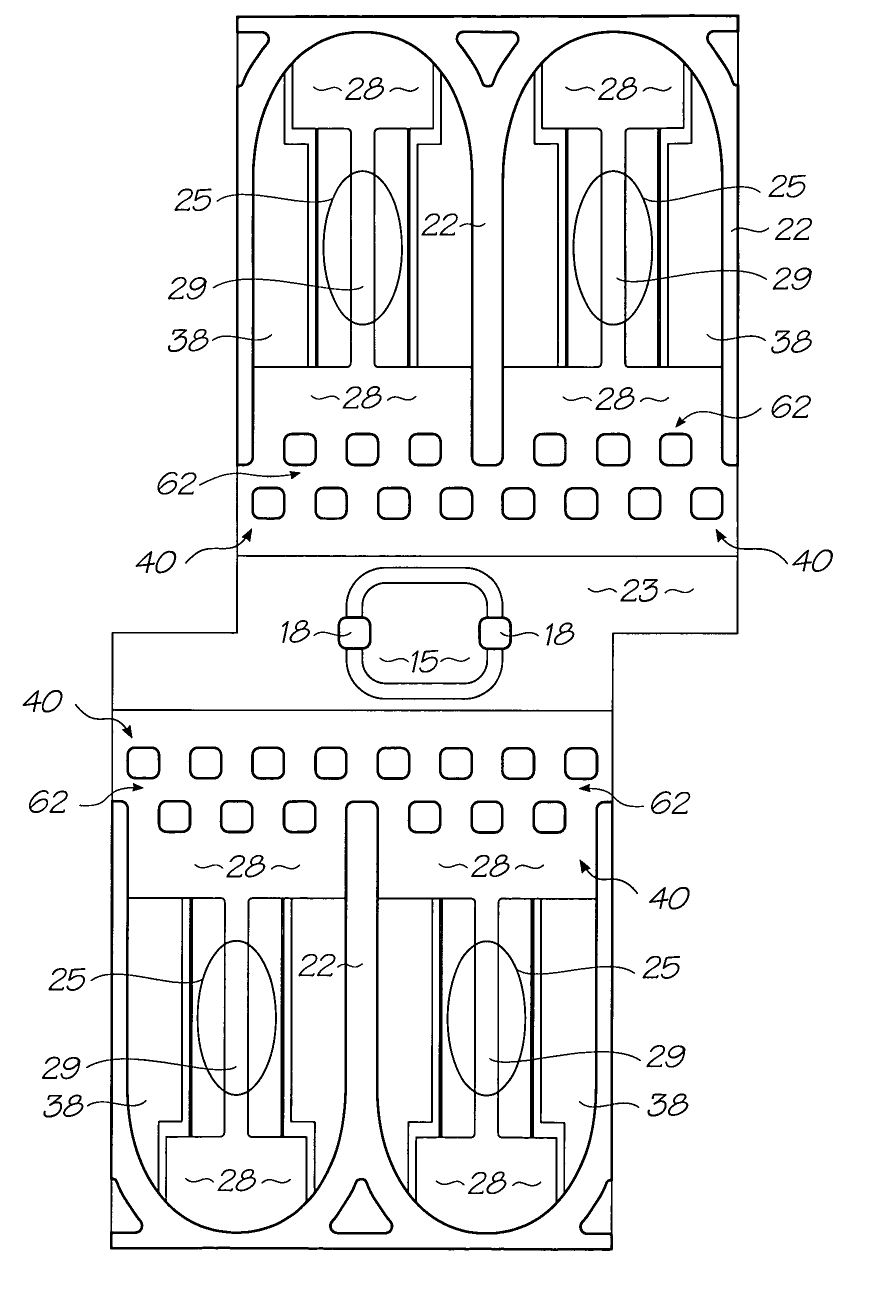
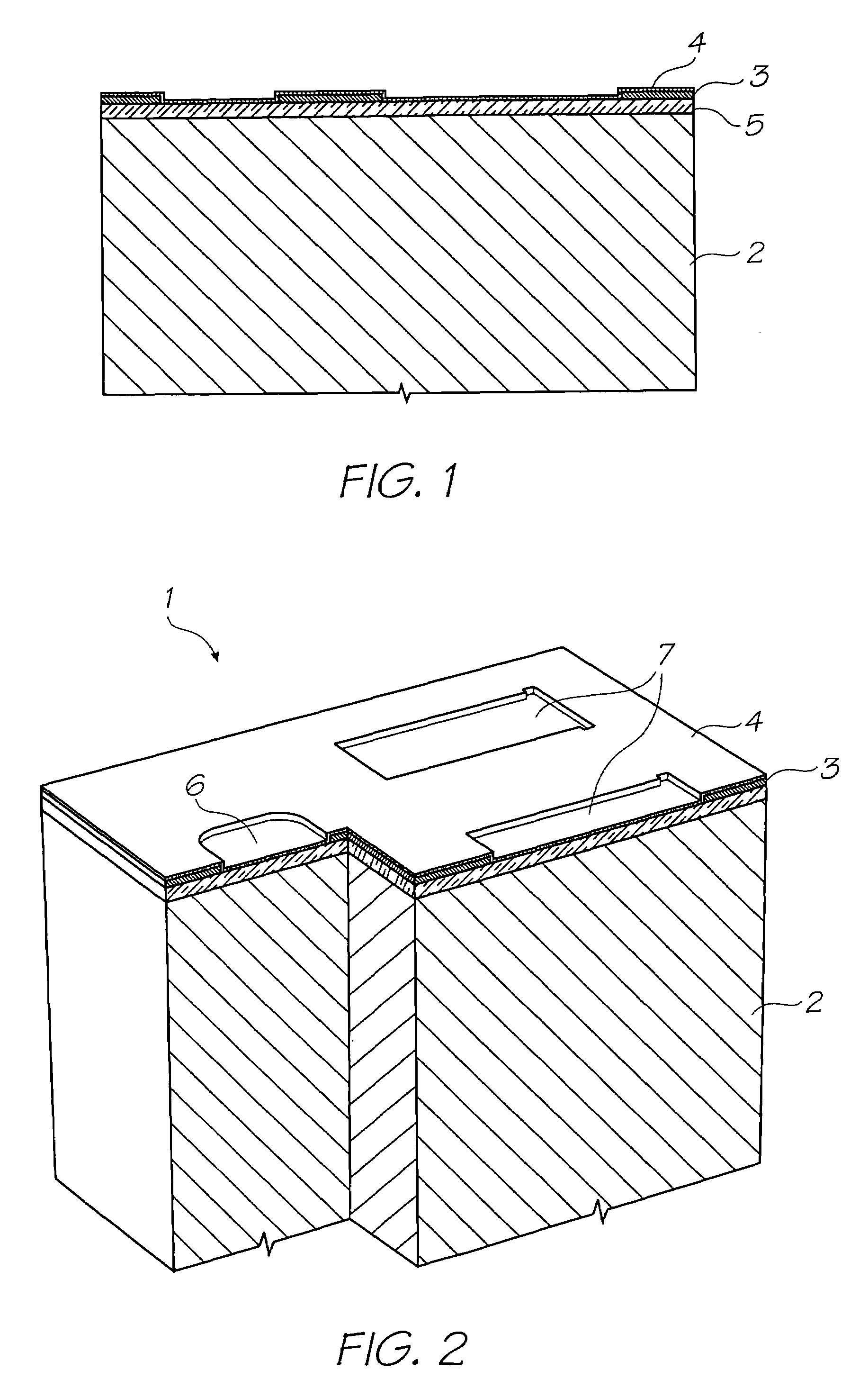
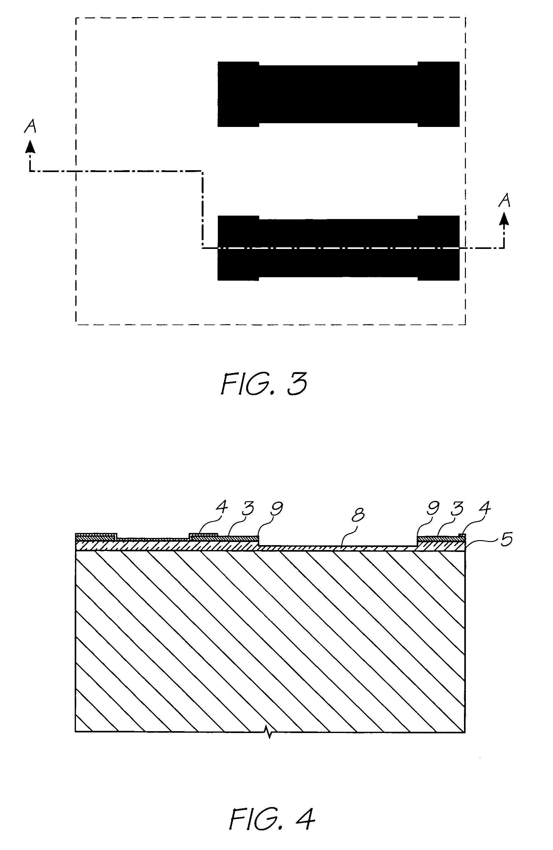
MNN MPN Series Parts List1.Nozzle Unit Cell2.Silicon Wafer3.Topmost Aluminium Metal Layer in the CMOS metal layers4.Passivation Layer5.CVD Oxide Layer6.Ink Inlet Opening in Topmost Aluminium Metal Layer 3.7.Pit Opening in Topmost Aluminium Metal Layer 3.8.Pit9.Electrodes10.SAC1 Photoresist Layer11.Heater Material (TiAlN)12.Thermal Actuator13.Photoresist Layer14.Ink Inlet Opening Etched Through Photo Resist Layer15.Ink Inlet Passage16.SAC2 Photoresist Layer17.Chamber Side Wall Openings18.Front Channel Priming Feature19.Barrier Formation at Ink Inlet20.Chamber Roof Layer21.Roof22.Sidewalls23.Ink Conduit24.Nozzle Chambers25.Elliptical Nozzle Rim25(a) Inner Lip25(b) Outer Lip26.Nozzle Aperture27.Ink Supply Channel28.Contacts29.Heater Element.30.Bubble cage32.bubble retention structure34.ink permeab...


PUM


Abstract

An inkjet printhead with an array of ink chambers, each having a nozzle and an actuator for ejecting ink through the nozzle; a plurality of ink inlets in fluid communication with the ink chambers; and, at least one priming feature extending through each of the ink inlets; such that, the surface tension of an ink meniscus at the ink inlet acts to draw the ink out of the inlet and partially along the flow path toward the ink chambers.By introducing a priming feature into the plane of the inlet aperture, the surface tension in the ink meniscus can be redirected to pull the ink along the intend flow path rather than push it back into the inlet.

Description

FIELD OF THE INVENTION[0001]The present invention relates to the field of inkjet printers and discloses an inkjet printing system using printheads manufactured with micro-electromechanical systems (MEMS) techniques.CO-PENDING APPLICATIONS[0002]The following applications have been filed by the Applicant simultaneously with the present application:[0003]11 / 24667611 / 24667711 / 2466781124667911 / 24668011 / 24668111 / 24671411 / 24671311 / 24668911 / 24667111 / 24667011 / 24666911 / 24670411 / 24671011 / 24668811 / 24671611 / 24671511 / 24670711 / 24670611 / 24670511 / 24670811 / 24669311 / 24669211 / 24669611 / 24669511 / 24669411 / 24668711 / 24671811 / 24668511 / 24668611 / 24670311 / 24669111 / 24671111 / 24671211 / 24671711 / 24670911 / 24670011 / 24670111 / 24670211 / 24666811 / 24669711 / 24669811 / 24669911 / 24667511 / 24667411 / 24666711 / 24668411 / 24667211 / 24667311 / 24668311 / 246682[0004]The disclosures of these applications are incorporated herein by reference.CROSS REFERENCES TO RELATED APPLICATIONS[0005]Various methods, systems and apparatus relating to the pre...

Claims


Application Information

Patent Timeline
Patent Type & Authority Patents(United States)
IPC IPC(8): B41J2/175
CPCB41J2/1404B41J2/1603B41J2/1628B41J2/1631B41J2/1639B41J2/1642B41J2/1645B41J2002/14403B41J2002/14475
Inventor SILVERBROOK, KIA
Owner SILVERBROOK RES PTY LTD
Why Eureka
Try Eureka