Printhead with inlet filter for ink chamber

a technology of ink chamber and inlet filter, which is applied in the field of printing heads, can solve the problems of clogging of nozzles from dried ink and contaminants in ink, serious damage to nozzle operation, and gas bubbles entrapped in ink flow, so as to reduce the amount of wafer area lost, increase nozzle density, and reduce the effect of wafer loss

Active Publication Date: 2007-04-12
SILVERBROOK RES PTY LTD +1
View PDF13 Cites 15 Cited by
  • Summary
  • Abstract
  • Description
  • Claims
  • Application Information

AI Technical Summary

Benefits of technology

[0079] The conduits for distributing ink to every ink chamber in the array can occupy a significant proportion of the wafer area. This can be a limiting factor for nozzle density on the printhead. By making some ink chambers part of the ink flow path to other ink chambers, while keeping each chamber sufficiently free of fluidic cross talk, reduces the amount of wafer area lost to ink supply conduits.
[0080] For the purpose of increasing nozzle density it is also advantageous to use elongate actuators. Thinner actuators allow the ink chamber to be thinner and therefore the entire unit cell of the printhead to be smaller in one dimension at least. Accordingly adjacent n...

Problems solved by technology

Clogging is one of the principle causes of nozzle failure.
Nozzles can clog from dried ink and contaminant...

Method used


Image

  • Printhead with inlet filter for ink chamber
  • Printhead with inlet filter for ink chamber
  • Printhead with inlet filter for ink chamber

Examples


Embodiment Construction

[0440] In the description than follows, corresponding reference numerals relate to corresponding parts. For convenience, the features indicated by each reference numeral are listed below.

MNN MPN Series Parts List

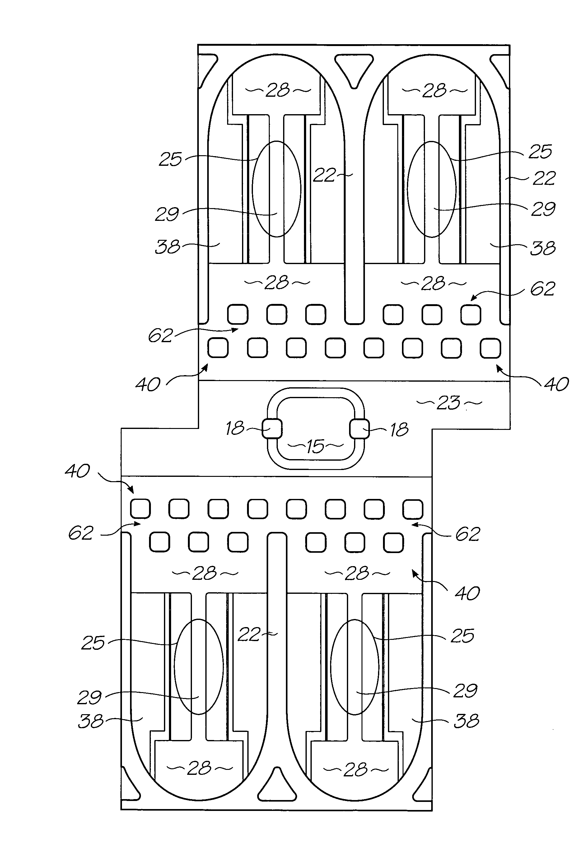
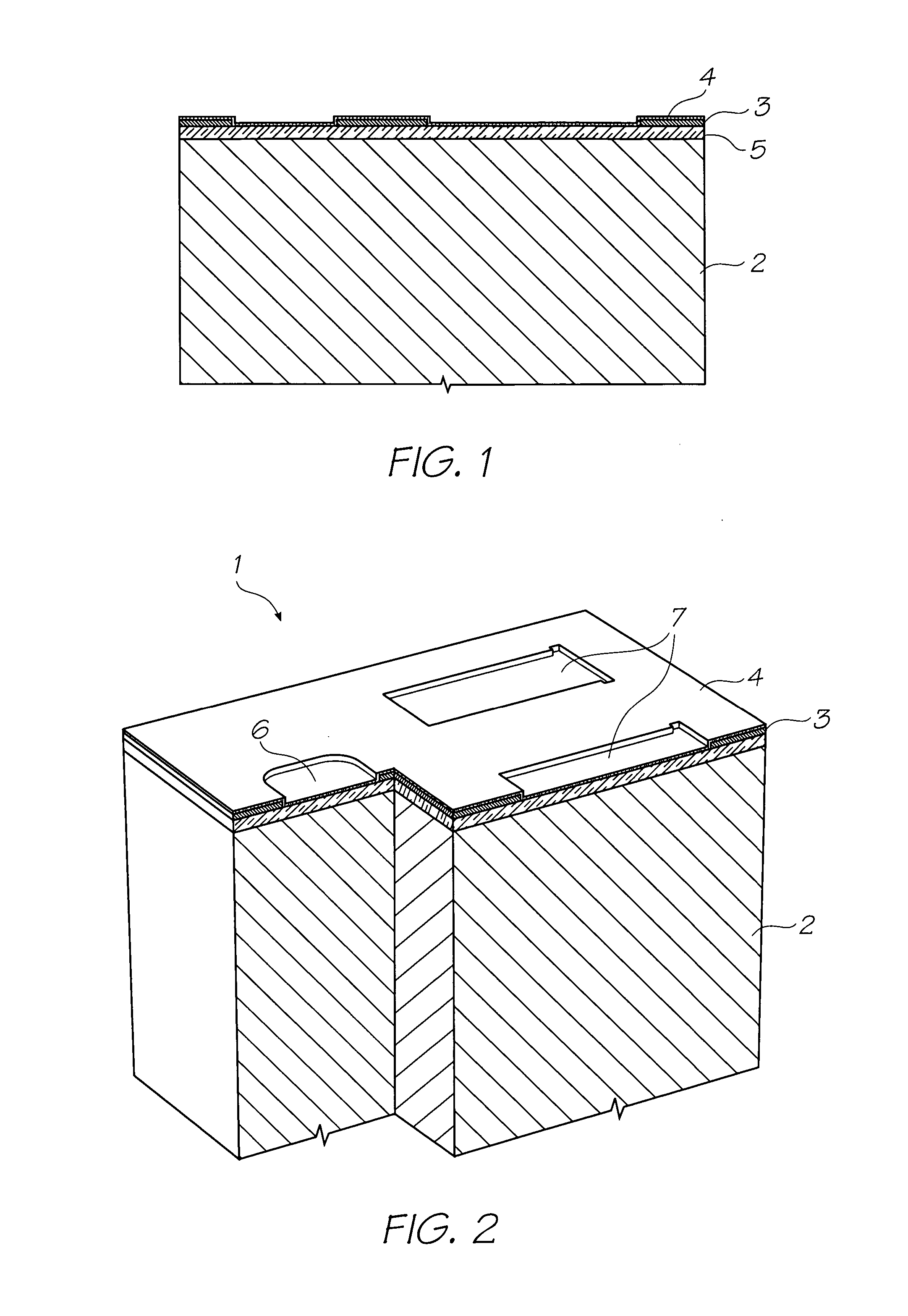
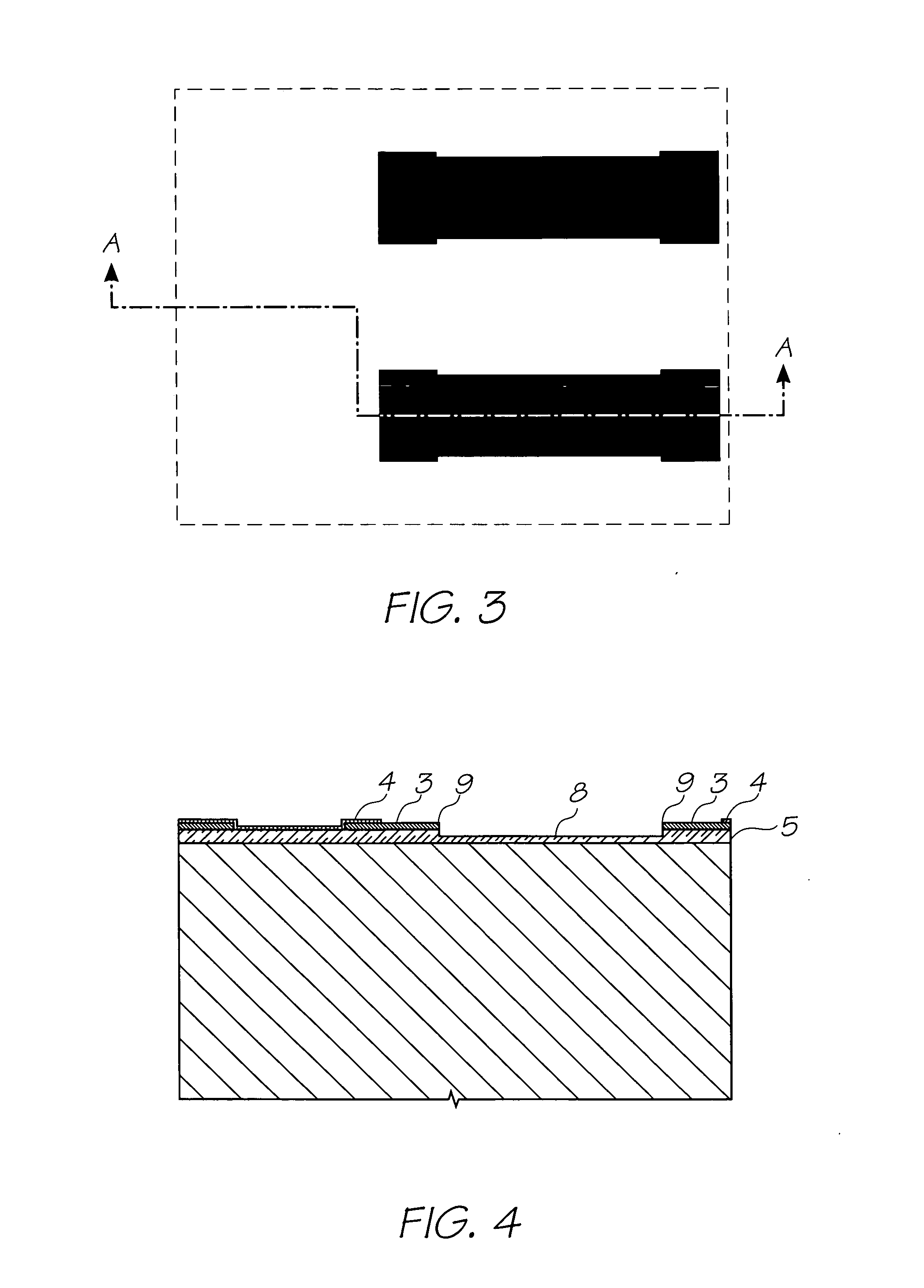
[0441]1. Nozzle Unit Cell [0442]2. Silicon Wafer [0443]3. Topmost Aluminium Metal Layer in the CMOS metal layers [0444]4. Passivation Layer [0445]5. CVD Oxide Layer [0446]6. Ink Inlet Opening in Topmost Aluminium Metal Layer 3. [0447]7. Pit Opening in Topmost Aluminium Metal Layer 3. [0448]8. Pit [0449]9. Electrodes [0450]10. SAC1 Photoresist Layer [0451]11. Heater Material (TiAlN) [0452]12. Thermal Actuator [0453]13. Photoresist Layer [0454]14. Ink Inlet Opening Etched Through Photo Resist Layer [0455]15. Ink Inlet Passage [0456]16. SAC2 Photoresist Layer [0457]17. Chamber Side Wall Openings [0458]18. Front Channel Priming Feature [0459]19. Barrier Formation at Ink Inlet [0460]20. Chamber Roof Layer [0461]21. Roof [0462]22. Sidewalls [0463]23. Ink Conduit [0464]24. Nozzle...


PUM


Abstract

An inkjet printhead with an array of ink chambers, each having a nozzle, an actuator for ejecting ink through the nozzle, an inlet opening allowing ink to refill the chamber and a filter structure at the inlet opening; wherein, the filter structure has rows of obstructions extending transverse to the flow direction through the opening, the obstructions in each row being spaced such that they are out of registration with the obstructions in an adjacent row with respect to the flow direction. Filtering the ink as it enters the chamber removes the contaminants and bubbles but it also retards ink flow into the chamber. The present invention uses a filter structure that has rows of obstructions in the flow path. The rows are offset with respect to each other to induce turbulence. This has a minimal effect on the nozzle refill rate but the air bubbles or other contaminants are likely to be retained by the obstructions.

Description

CROSS REFERENCE TO RELATED APPLICATIONS [0001] Various methods, systems and apparatus relating to the present invention are disclosed in the following U.S. patents / patent applications filed by the applicant or assignee of the present invention: 09 / 517539656685809 / 11276263319466246970644252509 / 51738409 / 505951637435409 / 51760809 / 50514710 / 20356467578326334190674533109 / 51754110 / 20355910 / 20356010 / 63626310 / 63628310 / 86660810 / 90288910 / 90283310 / 94065310 / 94285810 / 72718110 / 72716210 / 72716310 / 72724510 / 72720410 / 72723310 / 72728010 / 72715710 / 72717810 / 72721010 / 72725710 / 72723810 / 72725110 / 72715910 / 72718010 / 72717910 / 72719210 / 72727410 / 72716410 / 72716110 / 72719810 / 72715810 / 75453610 / 75493810 / 72722710 / 72716010 / 93472011 / 212,70210 / 296522679521510 / 29653509 / 57510910 / 29652509 / 57511009 / 607985639833263945736622923674776010 / 18945910 / 88488110 / 94394110 / 94929411 / 03986611 / 12301111 / 12301011 / 14476911 / 14823710 / 92284610 / 92284510 / 85452110 / 85452210 / 85448810 / 85448710 / 85450310 / 85450410 / 85450910 / 85451010 / 85449610 / 85449710 / 85449510...

Claims


Application Information

Patent Timeline
IPC IPC(8): B41J2/175
CPCB41J2/1404B41J2/1433B41J2/1603B41J2/1628B41J2/1631B41J2/1639B41J2/1642B41J2/1645B41J2002/14403B41J2002/14475B41J2202/11B41J2202/07
Inventor SILVERBROOK, KIA
Owner SILVERBROOK RES PTY LTD
Why Eureka
Try Eureka