Inkjet printhead with multi-nozzle chambers

a multi-nozzle chamber, inkjet printing technology, applied in the direction of printing, inking apparatus, etc., can solve the problems of affecting the quality of printing, the degree of misdirection of the ejector drop, and the control of the drop trajectory, so as to reduce the friction between the particles, and reduce the co-efficient of static friction

Inactive Publication Date: 2010-01-12
SILVERBROOK RES PTY LTD +1
View PDF15 Cites 29 Cited by
  • Summary
  • Abstract
  • Description
  • Claims
  • Application Information

AI Technical Summary

Benefits of technology

[0023]A planar thermal actuator, with contacts directly deposited onto the CMOS electrodes and suspended heater element, avoids hotspots caused by vertical or inclined surfaces so that the contacts can be much smaller structures without acceptable increases in resistive losses. Low resistive losses preserves the efficient operation of a suspended heater element and the small contact size is convenient for close nozzle packing on the printhead.
[0386]Optionally, the nozzle plate has an exterior surface with formations for reducing its co-efficient of static friction (known as ‘stiction’).

Problems solved by technology

One of the perennial problems with inkjet printing is the control of drop trajectory as it is ejected from the nozzle.
With every nozzle, there is a degree of misdirection in the ejected drop.
Depending on the degree of misdirection, this can be detrimental to print quality.

Method used


Image

  • Inkjet printhead with multi-nozzle chambers
  • Inkjet printhead with multi-nozzle chambers
  • Inkjet printhead with multi-nozzle chambers

Examples


Embodiment Construction

[0444]In the description than follows, corresponding reference numerals relate to corresponding parts. For convenience, the features indicated by each reference numeral are listed below.

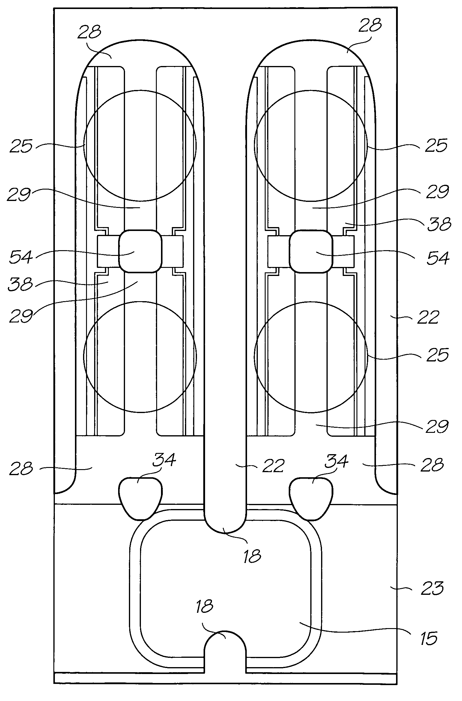
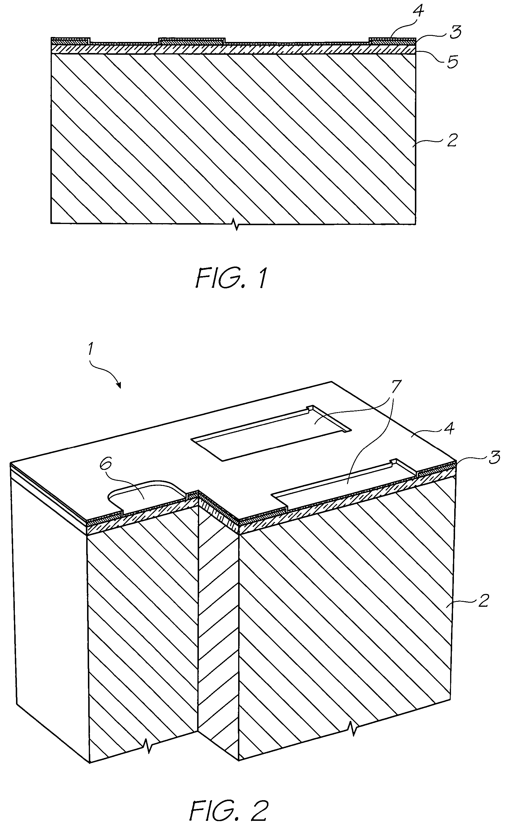
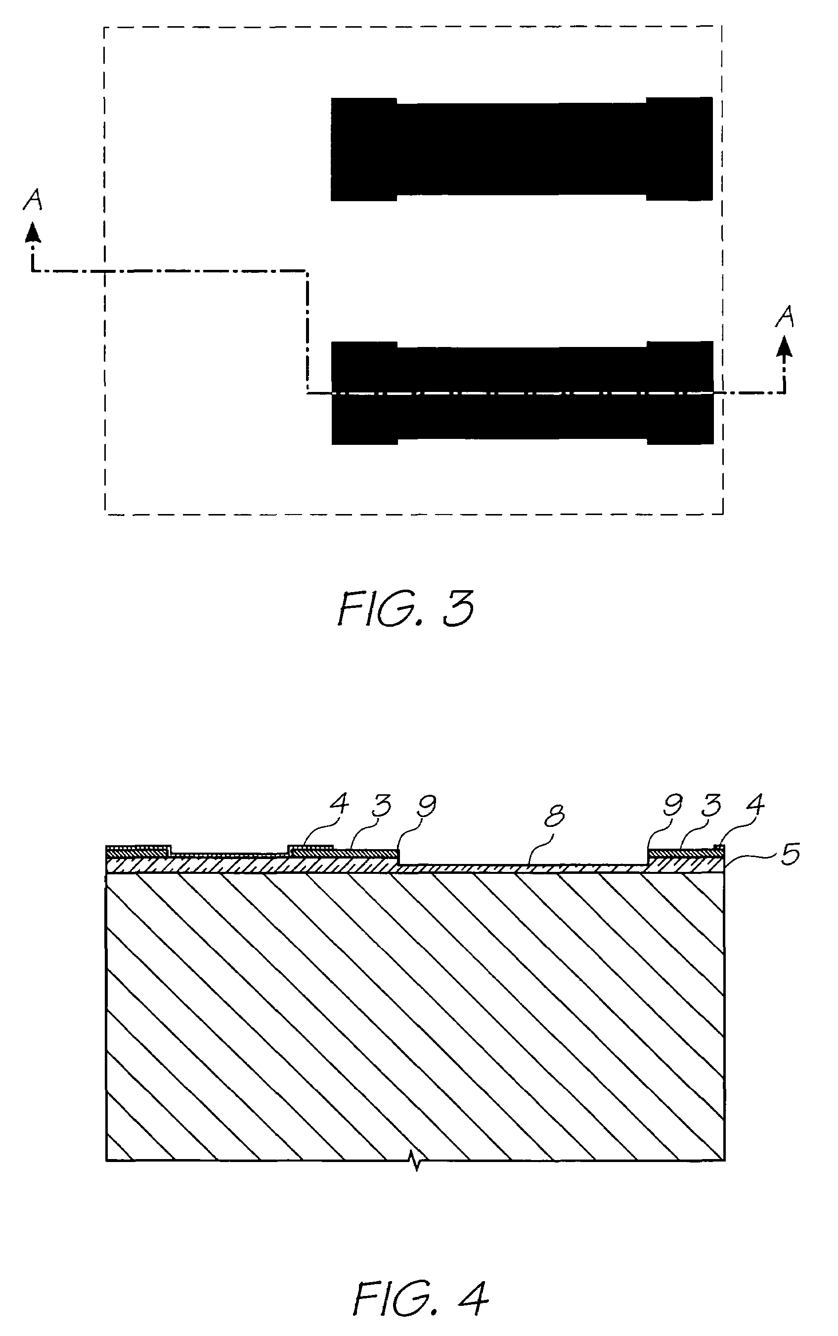
MNN MPN Series Parts List

[0445]1. Nozzle Unit Cell[0446]2. Silicon Wafer[0447]3. Topmost Aluminium Metal Layer in the CMOS metal layers[0448]4. Passivation Layer[0449]5. CVD Oxide Layer[0450]6. Ink Inlet Opening in Topmost Aluminium Metal Layer 3.[0451]7. Pit Opening in Topmost Aluminium Metal Layer 3.[0452]8. Pit[0453]9. Electrodes[0454]10. SAC1 Photoresist Layer[0455]11. Heater Material (TiAlN)[0456]12. Thermal Actuator[0457]13. Photoresist Layer[0458]14. Ink Inlet Opening Etched Through Photo Resist Layer[0459]15. Ink Inlet Passage[0460]16. SAC2 Photoresist Layer[0461]17. Chamber Side Wall Openings[0462]18. Front Channel Priming Feature[0463]19. Barrier Formation at Ink Inlet[0464]20. Chamber Roof Layer[0465]21. Roof[0466]22. Sidewalls[0467]23. Ink Conduit[0468]24. Nozzle Chambers[0469]25. Ellipti...


PUM


Abstract

An inkjet printhead with multiple nozzles in each ink chamber. By giving the chamber multiple nozzles, each nozzle ejects drops of smaller volume, and having different misdirections. Several small drops misdirected in different directions are less detrimental to print quality than a single relatively large misdirected drop.

Description

FIELD OF THE INVENTION[0001]The present invention relates to the field of inkjet printers and discloses an inkjet printing system using printheads manufactured with micro-electromechanical systems (MEMS) techniques.CO-PENDING APPLICATIONS[0002]The following applications have been filed by the Applicant simultaneously with the present application:[0003]11 / 246,67611 / 246,67711 / 246,67811 / 246,67911 / 246,68011 / 246,68111 / 246,71411 / 246,71311 / 246,68911 / 246,67111 / 246,67011 / 246,66911 / 246,70411 / 246,71011 / 246,68811 / 246,71611 / 246,7157,367,6487,370,93611 / 246,70511 / 246,70811 / 246,69311 / 246,69211 / 246,69611 / 246,69511 / 246,69411 / 246,6877,322,68111 / 246,68611 / 246,70311 / 246,69111 / 246,71111 / 246,69011 / 246,71211 / 246,71711 / 246,70911 / 246,70011 / 246,70111 / 246,70211 / 246,66811 / 246,69711 / 246,69811 / 246,69911 / 246,67511 / 246,67411 / 246,6677,303,93011 / 246,67211 / 246,67311 / 246,68311 / 246,682[0004]The disclosures of these co-pending applications are incorporated herein by reference.CROSS REFERENCES TO RELATED APPLICATIONS[0005...

Claims


Application Information

Patent Timeline
Patent Type & Authority Patents(United States)
IPC IPC(8): B41J2/04B41J2/05
CPCB41J2/1642B41J2/1645B41J2/1404B41J2/1601B41J2/1628B41J2/1631B41J2/1639B41J2002/14403B41J2002/14475B41J2202/11
Inventor SILVERBROOK, KIA
Owner SILVERBROOK RES PTY LTD
Why Eureka
Try Eureka