System for degassing muds and for analysing the gases contained in the muds

a technology of mud degassing and mud gas, which is applied in the field of system for degassing mud and analysing the gases contained in the mud, can solve the problems of difficult detection of gases, inconvenient, and inability to adjust, and achieve the effect of reliable, precise, quantitative and fast manner

Inactive Publication Date: 2008-12-16
GEOLOG
View PDF13 Cites 32 Cited by
  • Summary
  • Abstract
  • Description
  • Claims
  • Application Information

AI Technical Summary

Benefits of technology

[0014]The object of the invention is to overcome these drawbacks and, more particularly, to enable degassing of drilling muds and analysis of the extracted gases in a reliable, precise, quantitative and fast manner, in particular by means of a better extraction of the light gases and even more so of the heavy gases.

Problems solved by technology

Other non hydrocarbon revealing gases, for example Argon, H2S and CO2, can provide complementary information of geological nature on the interest of the drilling-hole, but these gases are often more difficult to detect.
However, this method is not suitable for the difficult conditions encountered in the field when drilling operations are performed, as such a system is fragile and does not resist large temperature variations.
The drawback of this method is that the propeller stirs the mud in the tank in very inhomogeneous manner.
Consequently, this method does not enable extraction yields as high as what is desirable to be obtained, in particular for heavy gases corresponding to certain types of hydrocarbons.
This method can present a risk of chemical modification of the gases or of inflammation.
These known techniques present the drawback of only extracting a fraction of the light gases contained in the drilling muds and do not enable heavy gases containing six, seven or eight or more carbon atoms to be extracted.

Method used


Image

  • System for degassing muds and for analysing the gases contained in the muds
  • System for degassing muds and for analysing the gases contained in the muds
  • System for degassing muds and for analysing the gases contained in the muds

Examples


Embodiment Construction

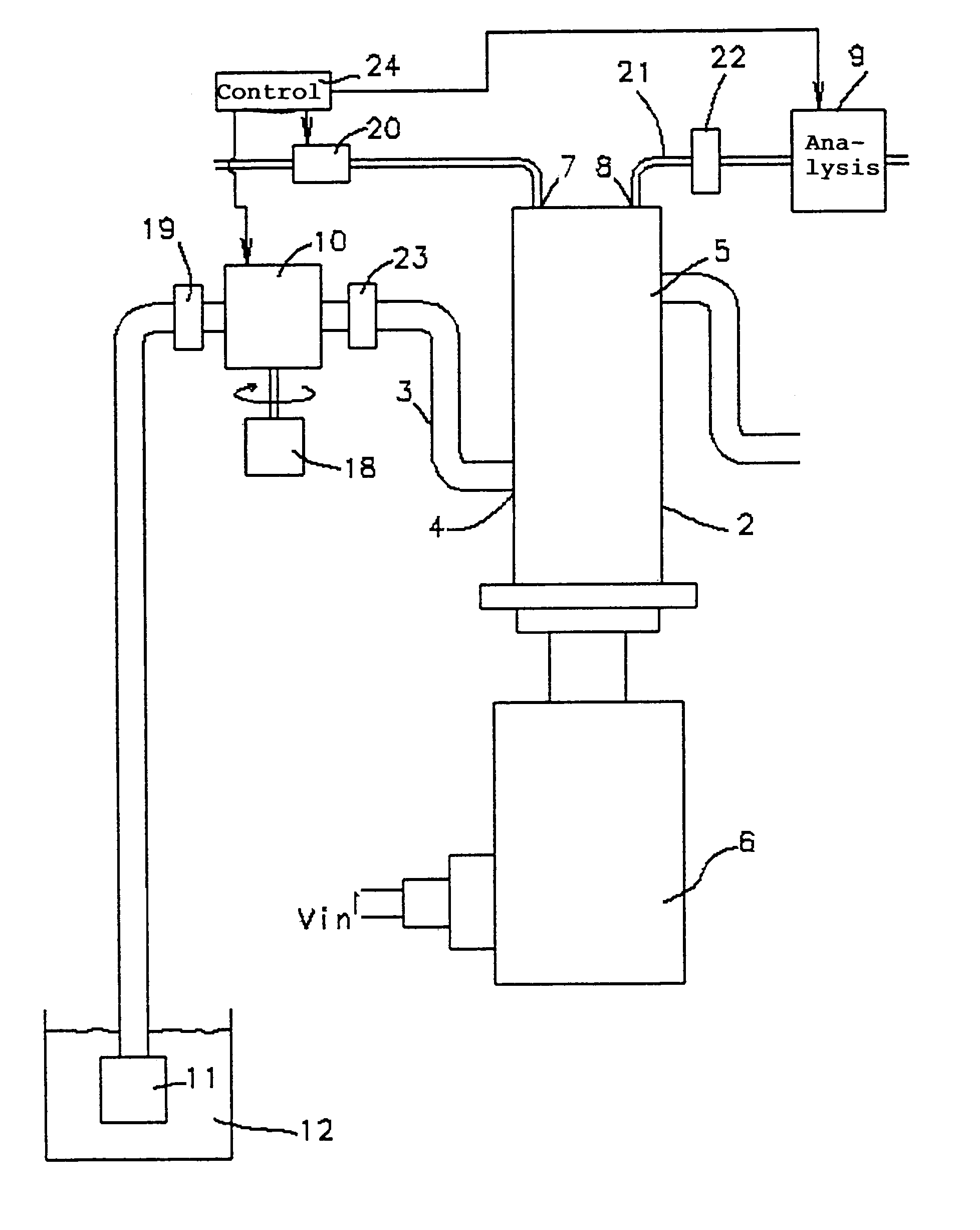
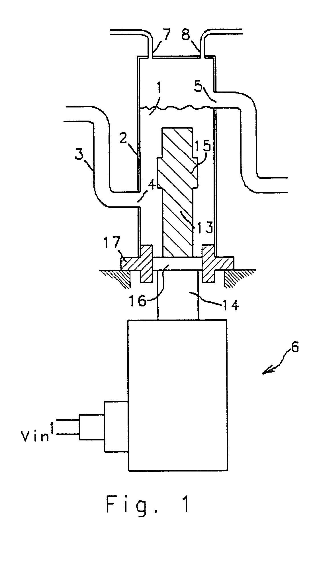
[0019]In FIG. 1, mud 1 is input to a tank 2 via a feed pipe 3 connected to a first inlet 4 arranged at the bottom part of a side wall of the tank 2. It is removed via a first outlet 5 arranged at the top part of a side wall of the tank 2 enabling a preset constant volume of mud 1 to be guaranteed in the tank 2 by overflow. The mud thus fills the tank 2 partially in the bottom part up to the level of the first outlet 5. An ultrasonic electroacoustic transducer 6 is designed to generate an acoustic energy field in the mud 1 contained in the tank 2 and thus to extract the gases from the mud. A carrier gas is injected via a second inlet 7 of the tank and removed via a second outlet 8 carrying the extracted gases with it. The second inlet 7 and second outlet 8 are arranged above the first outlet 5 of the mud so that the carrier and extracted gases occupy the top part of the tank 2.

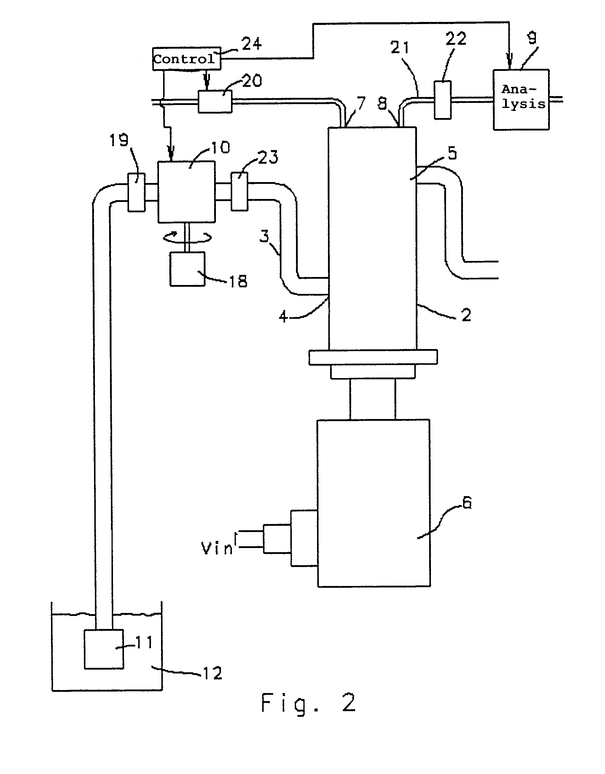
[0020]As represented in FIG. 2, the second outlet 8 is connected to an apparatus 9 for physico-chemical anal...


PUM

PropertyMeasurementUnit
densityaaaaaaaaaa
flow rateaaaaaaaaaa
flow rateaaaaaaaaaa

Abstract

A tank is fed with mud via a first inlet and the mud is removed via a first outlet. An ultrasonic electroacoustic transducer generates an acoustic energy field in the mud contained in the tank so as to extract the gases from the mud. A carrier gas is injected via a second inlet of the tank and a physico-chemical analysis apparatus of the extracted gases is connected to a second outlet of the tank designed for the carrier gas and the extracted gases. The flow rate of mud fed to the tank is regulated to a constant value and the volume of mud in the tank is constant. The mud can be constituted by oil prospecting drilling mud, the gases to be extracted then being oil revealing gases. The mud feed and injection of carrier gas can be synchronized so as to enable continuous analysis or batch analysis.

Description

BACKGROUND OF THE INVENTION[0001]The invention relates to a system for degassing muds and for analysing the gases contained in the muds, a system comprising:[0002]a tank comprising a first inlet and a first outlet for the mud,[0003]feed means of the mud, connected to the first inlet of the tank,[0004]means for extracting the gases from the mud contained in the tank,[0005]means for injecting a carrier gas, connected to a second inlet of the tank,[0006]means for physico-chemical analysis of the extracted gases, connected to a second outlet of the tank, designed for the carrier gas and the extracted gases.STATE OF THE ART[0007]The invention concerns extraction and analysis of gases present in muds and applies in particular to detection of revealing gases such as hydrocarbon and non hydrocarbon gases present in the drilling muds obtained when oil field prospecting operations are performed. For these prospecting operations, the practice is for drill-holes to be made and for the drilling ...

Claims


Application Information

Patent Timeline
Patent Type & Authority Patents(United States)
IPC IPC(8): G01N15/06B01D51/08G01N7/00E21B47/00E21B47/10B01D19/00E21B21/06G01N1/10G01N1/22G01N33/28
CPCB01D19/0005E21B21/067G01N1/2247G01N33/2823G01N2001/1025G01N2001/2267
Inventor KERHERVE, JOSEPHLHERMET, NICOLAS
Owner GEOLOG
Why Eureka
Try Eureka