Method and apparatus for simulating the appearance of a neon sign

a technology of neon signs and apparatus, applied in the field of neon signs, can solve problems such as high temperature inside the tube, and achieve the effect of reducing the visibility of the opaque portion

Active Publication Date: 2008-12-23
KAOH ANDY K F
View PDF37 Cites 27 Cited by
  • Summary
  • Abstract
  • Description
  • Claims
  • Application Information

AI Technical Summary

Benefits of technology

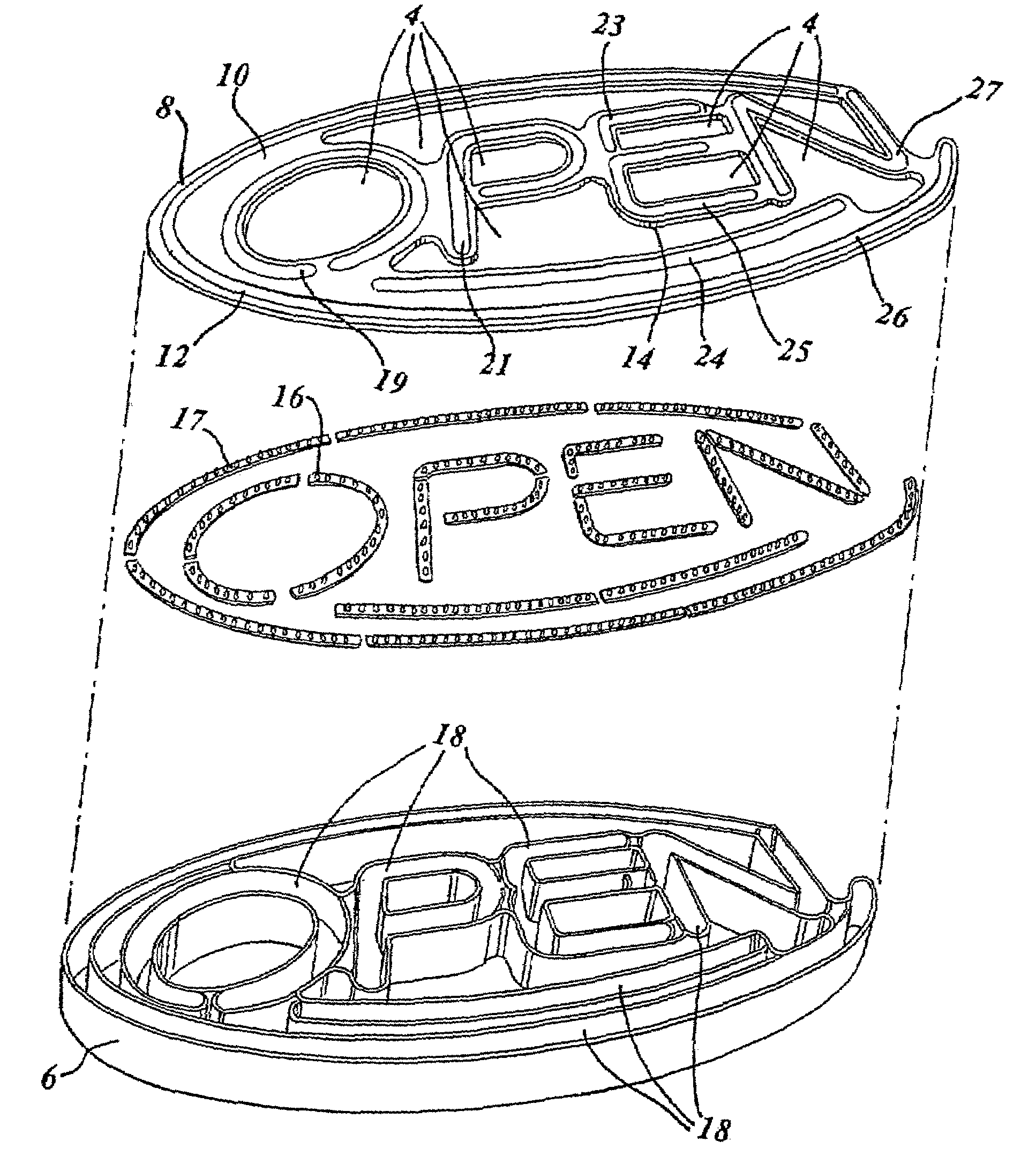
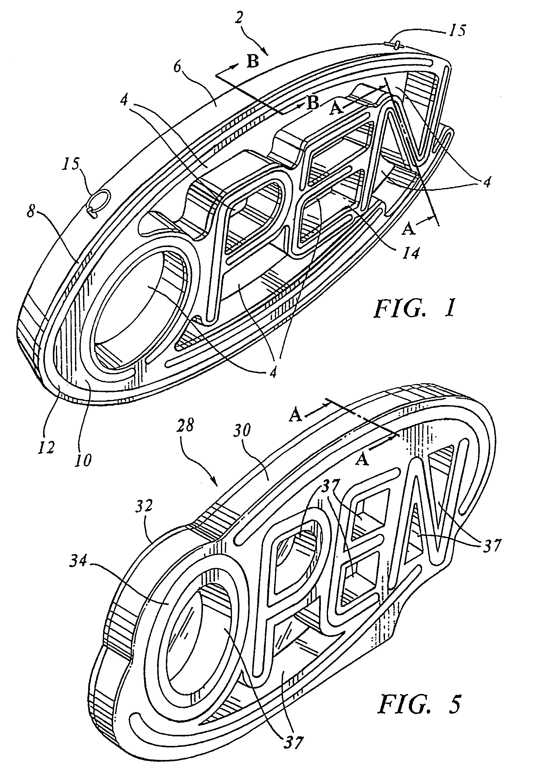
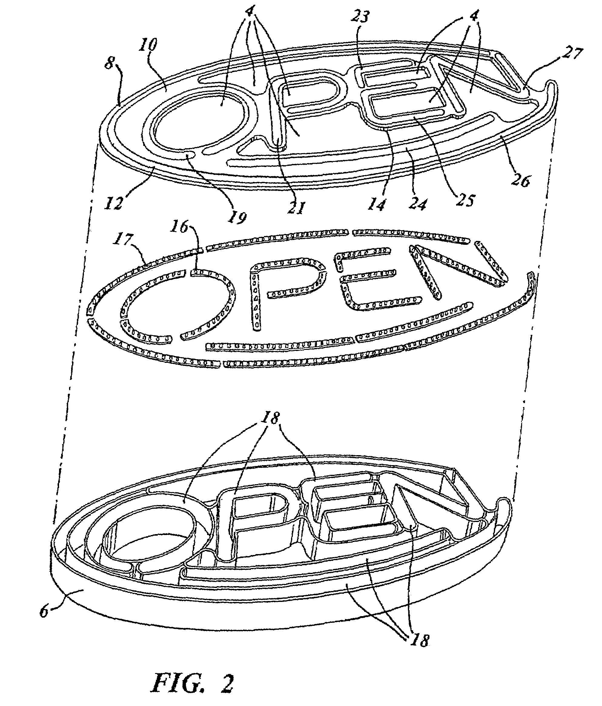
[0011]The opaque portion of the housing has a shiny interior surface that reflects light emitted from the LEDs. The outer portion of the housing has a dark textured appearance making the surface appear flat and dull in stark contrast with the illuminated translucent portion. This contrast minimizes the visibility of the opaque portion of the housing creating a realistic neon like illumination particularly at night or in a dark setting.
[0012]The housing has a form that profiles the contours of the message to be conveyed. This contoured shape creates a more authentic neon sign like appearance. The housing is compartmentalized to focus the LED energy and prevent unwanted mixing of light from different colored LEDs.
[0013]One embodiment of the invention has an open structure wherein the desired message is cantilevered to permit a viewer to see through openings in the supporting housing adjacent the openings to further emphasize a neon sign effect.

Problems solved by technology

During evacuation a high voltage pulse is applied to the electrodes resulting in arcing from one electrode the other creating a high temperature inside the tube.

Method used


Image

  • Method and apparatus for simulating the appearance of a neon sign
  • Method and apparatus for simulating the appearance of a neon sign
  • Method and apparatus for simulating the appearance of a neon sign

Examples


Embodiment Construction

[0025]Reference will now be made in detail to the preferred embodiments of the invention which set forth the best modes contemplated to carry out the invention, examples of which are illustrated in the accompanying drawings. While the invention will be described in conjunction with the preferred embodiments, it will be understood that they are not intended to limit the invention to these embodiments. On the contrary, the invention is intended to cover alternatives, modifications and equivalents, which may be included within the spirit and scope of the invention as defined by the appended claims. Furthermore, in the following detailed description of the present invention, numerous specific details are set forth in order to provide a thorough understanding of the present invention. However, it will be obvious to one of ordinary skill in the art that the present invention may be practiced without these specific details. In other instances, well known methods, procedures, components, an...


PUM


Abstract

A plurality of light emitting diodes (LEDs) disposed in a customized housing produce bright colored light simulating the appearance of a neon sign. The housing includes an opaque portion that reflects light from the LEDs and a translucent portion shaped in the form of an image or lettering that diffuses light from the LEDs. The inside surface of the opaque portion has a polished reflective surface while the outside surface has a dull textured surface. Light emanating from the LEDs propagates through the translucent portion of the housing appearing to a viewer as a bright uniform and colorful light similar in appearance to the light emitted from a neon sign.

Description

BACKGROUND OF THE INVENTION[0001]1. Field of the Invention[0002]The invention relates generally to signage devices, and more particularly, to lighting devices that simulate the appearance of a neon gas light sign with solid state light emitters.[0003]2. Description of Related Art[0004]Advertisers and business establishments make extensive use of neon lights to convey a message and their appearances have become acceptable to customers. The bright, uniform, and colorful light distribution emitted from a neon light attracts attention making neon signs a good advertising medium. Neon signs have been used extensively for close to one hundred years.[0005]To construct a segment of a neon sign, an artisan can heat lead glass tubing using a small blow torch and can shape the lead glass tube into a desired shape. During the shaping process, the artisan attaches an electrode to each end of the tube. The artisan then attaches the tube to a manifold with a high quality vacuum pump. The pump evac...

Claims


Application Information

Patent Timeline
Patent Type & Authority Patents(United States)
IPC IPC(8): G09F13/28
CPCG09F13/22
Inventor KAOH, ANDY K. F.
Owner KAOH ANDY K F
Why Eureka
Try Eureka