
Auxiliary fuel and air supply in a carburetor

a technology of auxiliary fuel and air supply, which is applied in the direction of liquid fuel feeders, machines/engines, and separation processes, etc., can solve the problems of adding components, complexity, and cost to the carburetor, and eliminating the use of conventional choke valves, the effect of eliminating the steps of engine starting

Inactive Publication Date: 2008-12-23
WALBRO ENGINE MANAGEMENT
View PDF10 Cites 37 Cited by
  • Summary
  • Abstract
  • Description
  • Claims
  • Application Information

AI Technical Summary

Benefits of technology

[0007]At least some of the objects, features and advantages that may be achieved by at least certain embodiments of the invention include providing a carburetor with an auxiliary fuel and air supply apparatus that is automatically operable and does not require an operator to manually actuate a control valve to open or close a conduit of an auxiliary fuel and air supply apparatus, is compact, simple in operation, eliminates steps in engine starting, uses relatively few components, eliminates use of a conventional choke valve, enhances starting and warm up of an engine, supplies a relatively richer fuel and air mixture to an engine than normally supplied by a carburetor having a conventional choke valve, improves low speed stability of an engine, can be used with carburetor bodies originally designed for use with a conventional choke valve, and is of relatively simple design, economical manufacture and assembly, rugged, durable and reliable, and in service has a long useful life.

Problems solved by technology

Thus, the manual control valve and associated devices add components, complexity, and cost to the carburetor, and require separate manual valve actuation steps by an operator.

Method used


Image

  • Auxiliary fuel and air supply in a carburetor
  • Auxiliary fuel and air supply in a carburetor
  • Auxiliary fuel and air supply in a carburetor

Examples


Embodiment Construction

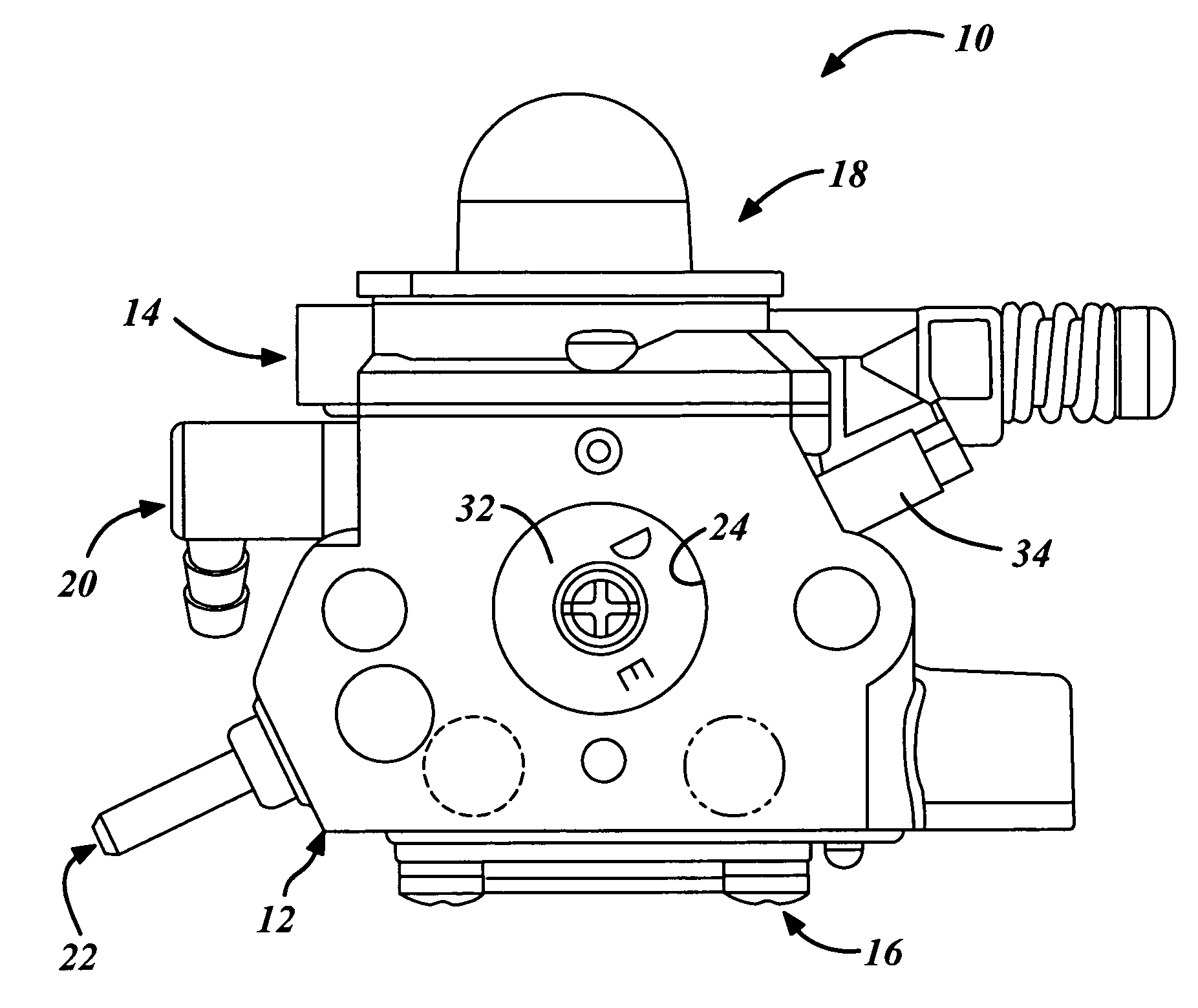
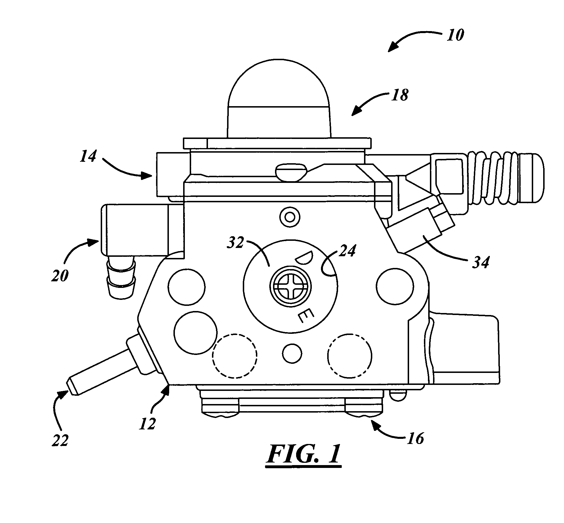
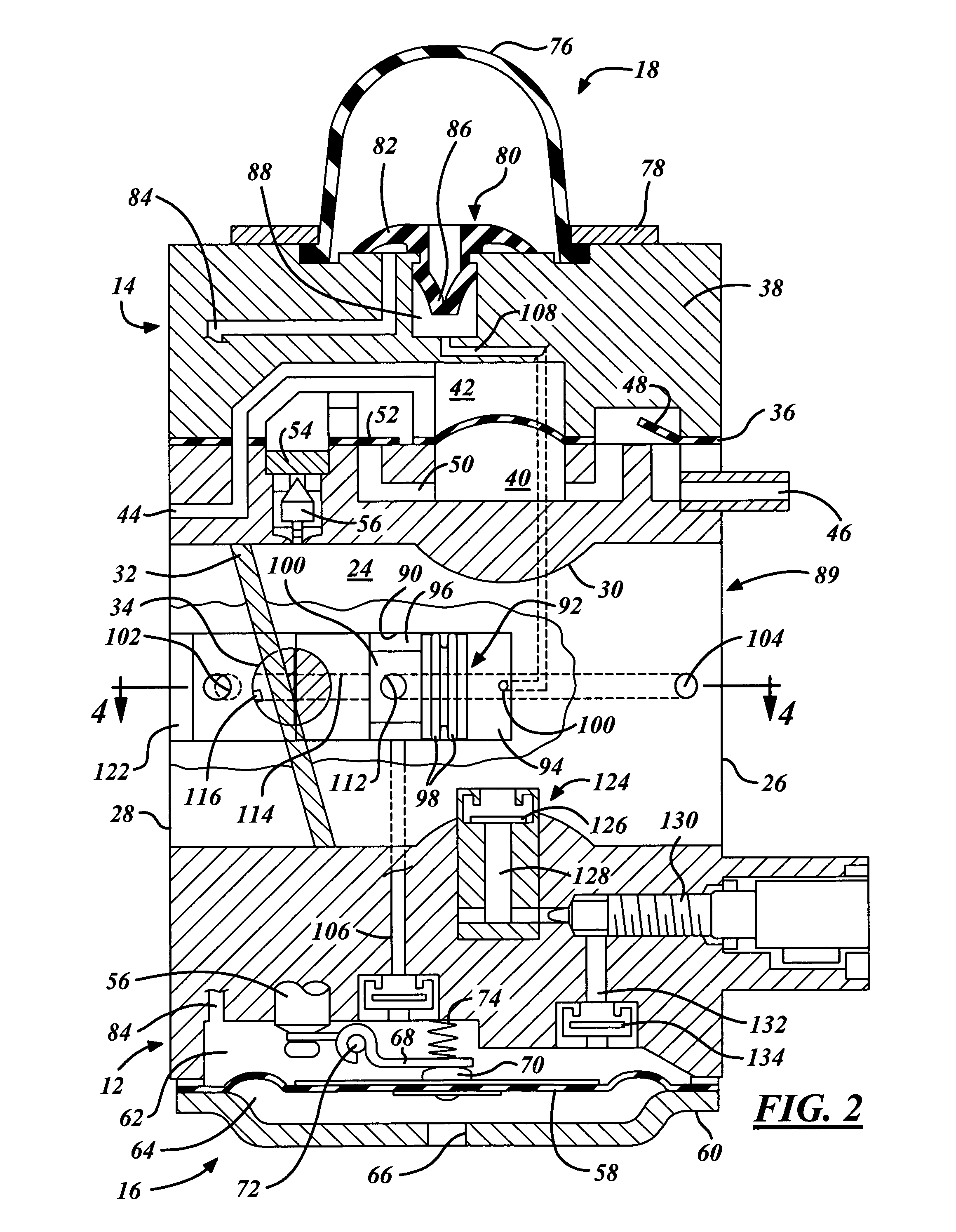
[0014]Referring in more detail to the drawings, FIG. 1 illustrates a carburetor 10 for use with an internal combustion engine (not shown). The carburetor 10 includes a main body 12, a fuel pump assembly 14 for pumping liquid fuel, a fuel metering assembly 16 for metering desired amounts of liquid fuel into the main body 12, and a fuel purge apparatus 18 for purging the fuel pump assembly 14 and the metering assembly 16 of stale fuel and any fuel vapor and air. The carburetor 10 may be similar in many respects to that described in U.S. Pat. No. 6,293,524, which is assigned to the assignee hereof and is incorporated by reference herein in its entirety.

[0015]The main body 12 may be composed of any suitable material but is preferably composed of metal such as cast aluminum or the like. The main body 12 provides structural support for the aforementioned assemblies 14, 16, 18 and various other components and passages as will be described in further detail herein below. Externally, the mai...


PUM

PropertyMeasurementUnit
pressureaaaaaaaaaa
flexibleaaaaaaaaaa
speed stabilityaaaaaaaaaa

Abstract

A carburetor includes a fuel and air mixing passage with a throttle valve therein, and a bore with a valve therein defining in part a valve actuation chamber and a separate fuel and air mixing chamber in communication with the fuel and air mixing passage at a location downstream of the throttle valve. A fuel passage and an air passage are in communication with the fuel and air mixing chamber. A purge apparatus is in communication with the valve actuation chamber and is operable to move the valve to an open position to open the fuel and air passages to the fuel and air mixing chamber such that a fuel and air mixture may flow from the fuel and air mixing chamber to the fuel and air mixing passage downstream of the throttle valve.

Description

FIELD OF THE INVENTION[0001]This invention relates generally to engine fuel systems, and more particularly to a carburetor.BACKGROUND OF THE INVENTION[0002]A carburetor is typically used to supply a fuel and air mixture to two stroke and four stroke internal combustion engines. For many applications where small two stroke engines are used, such as hand held power chainsaws, weed trimmers, leaf blowers, garden equipment and the like, a carburetor with both a diaphragm fuel pump and a diaphragm fuel metering system are often used.[0003]A so-called diaphragm carburetor generally includes a body having a mixing passage with an air inlet opening, and a fuel and air mixture outlet opening downstream of the air inlet opening. The diaphragm carburetor also typically includes a throttle valve disposed in the fuel and air mixing passage downstream of the air inlet opening for controlling delivery of a primary fuel and air mixture to the engine. A typical diaphragm fuel metering system include...

Claims


Application Information

Patent Timeline
Patent Type & Authority Patents(United States)
IPC IPC(8): F02M7/08
CPCF02M17/04Y10S261/08Y10S261/21
Inventor BRAUN, MATTHEW A.
Owner WALBRO ENGINE MANAGEMENT
Learn More