Voltage sensing hand tool

a hand tool and voltage sensing technology, applied in the field of electric sensing hand tools, can solve the problems of electrical hazards to both the worker and the associated electrical equipment, one particular hazard, injury to the worker, damage to the electrical equipment, etc., and achieve the effect of low cost and high degree of safety for the user

Inactive Publication Date: 2008-12-23
ECM IND LLC
View PDF23 Cites 16 Cited by
  • Summary
  • Abstract
  • Description
  • Claims
  • Application Information

AI Technical Summary

Benefits of technology

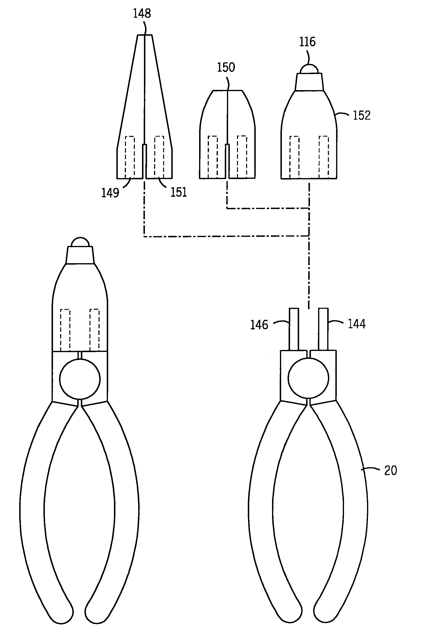
[0009]The present invention is a low cost, reliable and easy-to-use hand tool providing an alert signal to a user prior to contacting a live wire. The device of the present invention either permanently or temporarily integrates a non-contact voltage alert circuit and associated alarm circuitry into a hand tool, thereby providing a high degree of safety for the user. The alarm circuitry provides a visual or audio signal, alerting the user that contact with a live wire is about to be made.

Problems solved by technology

Not infrequently, however, through error or oversight, these circuits remain in an energized condition during maintenance, thereby presenting an electrical hazard to both the worker and to the associated electrical equipment.
One particular hazard is encountered when conductive hand tools such as wire strippers, cutters, pliers, screwdrivers and such are employed in maintenance procedures.
When these hand tools come into contact with the live electrical circuits, they can cause both injury to the worker and damage to the electrical equipment.
Such devices, however, require actual, physical contact with the live wire or circuit before the user is alerted.
These devices do not provide a sufficient warning to an unsuspecting user contacting a high voltage circuit to prevent injury or damage.
Furthermore, these devices do not provide any indication of contact with a live wire when the wire is insulated.
The test, therefore, does not solve the initial problem: erroneously or mistakenly forgetting to disable or verify disablement of the circuit before work is begun.
Neither of these prior art devices therefore can actively alert the user of the possibility of hazardous voltages on the wires, cables or other electrical devices prior to potentially dangerous contact.

Method used


Image

  • Voltage sensing hand tool
  • Voltage sensing hand tool
  • Voltage sensing hand tool

Examples


first embodiment

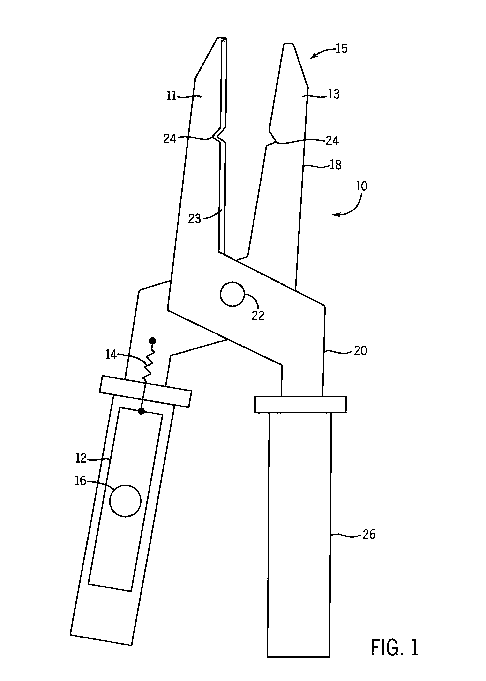
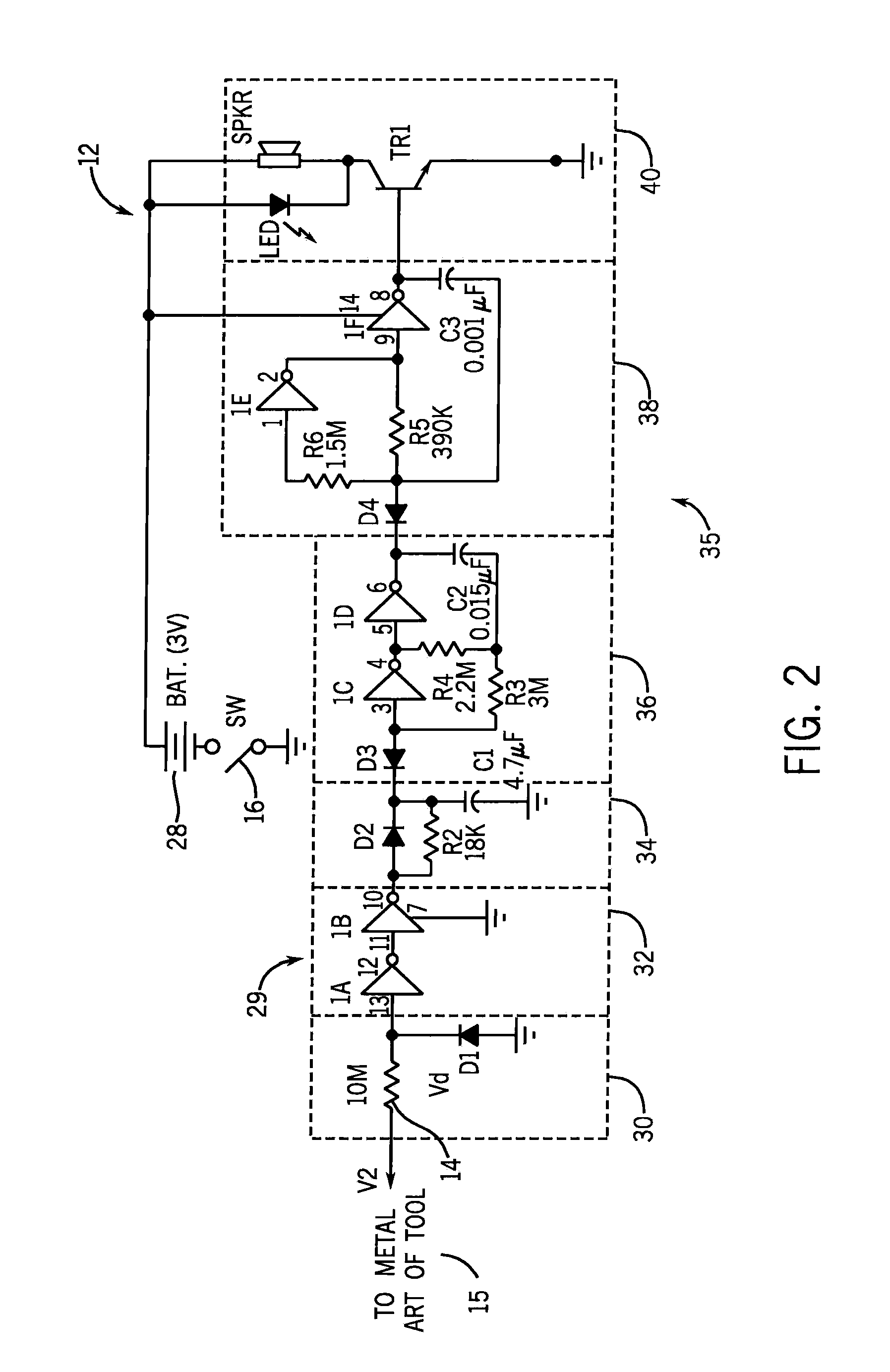
[0043]Referring now to the figures and more particularly to FIG. 1, a hand tool 10 constructed in accordance with the present invention is shown. The hand tool 10 generally comprises a functional tool end, hereafter the tool head 15, and one or more handles 20. As shown in FIG. 1, the hand tool 10 can be a wire cutter and stripper, wherein the head end 15 comprises first and second blade elements 11 and 13 rotatably coupled around a fastener 22. Each of the blade elements 11 and 13 comprises a conductive blade 18 and a handle 20. The blades 18 each include a cutting edge 23 for cutting a wire. Each cutting edge 23 includes a generally v-shaped or notched cutting edge 24 which, when the metal blades 18 are pivoted toward each other, provide cutting edges for stripping insulation from a wire. Each of the handles 20 may be an extension of the corresponding blades and is preferably covered with a plastic grip or other non-conductive covering material 26. A non-contact voltage alert circ...

second embodiment

[0055]Referring now to FIG. 3, a hand tool 10 constructed in accordance with the present invention is shown. Again the hand tool 10 is a wire stripper wherein like elements to those of FIG. 1 are numbered in accordance with the description of FIG. 1. The hand tool 10 of FIG. 3, however, does not include the push button 16 described above but rather includes a metal foil 42 inside the plastic covered handle 26. Referring now also to FIG. 4, a circuit diagram of the hand tool of FIG. 3 is shown, wherein elements are numbered in accordance with the description of FIG. 2, above. It can be seen that the metal foil 42 is coupled to the circuit common or ground of the voltage alert circuit 12. The metal foil 42 provides capacitive coupling to a user's hand and a conductive path for electrical current induced in the hand tool 10, thereby insuring that the current flow from the live electrical wire is through resistor 14 and the voltage alert circuit 12 and not via another path. As noted abo...


PUM


Abstract

A hand tool and an accessory which provide an alarm signal to a user as the tool or accessory approaches a live electrical wire are disclosed. The hand tool or accessory include a non-contact voltage sensing circuit. As the tool or accessory approaches a live electrical wire, the non-contact voltage sensing circuit detects the voltage, triggering an alarm circuit. The alarm circuit provides a visual or audio signal to the user. The hand tool can be selectively coupled to the tool head.

Description

CROSS-REFERENCE TO RELATED APPLICATION[0001]This application claims priority to U.S. Provisional Application Ser. No. 60 / 700,413, filed Jul. 19, 2005, and is a continuation-in-part of U.S. patent application Ser. No. 11 / 005,187 filed Dec. 6, 2004 now U.S. Pat. No. 7,295,130, which is a continuation-in-part of U.S. patent application Ser. No. 10 / 808,291 filed Mar. 24, 2004 now U.S. Pat. No. 6,844,819, which is a continuation of U.S. patent application Ser. No. 10 / 112,446, filed Mar. 28, 2002, now U.S. Pat. No. 6,731,218.FIELD OF INVENTION[0002]The present invention is generally directed to an electrical sensing tool More particularly, the present invention is directed to a voltage sensing hand tool that includes a non-contact voltage sensing circuit and an associated alarm circuit.BACKGROUND[0003]Electricians, technicians, maintenance people, and others who work with and around electrical distribution and wiring systems often work in the vicinity of energized electrical panels and wi...

Claims


Application Information

Patent Timeline
Patent Type & Authority Patents(United States)
IPC IPC(8): G08B21/00
CPCH02G1/005G01R29/0857
Inventor ONACHILLA, MICHAEL D.RADLE, PATRICK J.BROCKMAN, DARYL C.WIESEMANN, DAVID L.STEBER, GEORGE R.LUEBKE, THOMAS M.
Owner ECM IND LLC
Why Eureka
Try Eureka