Method of making molded coupler

a technology of molded couplers and connectors, which is applied in the direction of metal rolling stands, metal-working apparatus, nuclear energy welding apparatus, etc., can solve the problems of distorted flow channel dimensions, inconsistent coupling body dimensions, and problems such as the inability to meet the needs of the coupling body,

Active Publication Date: 2008-12-30
COLDER PRODS
View PDF19 Cites 87 Cited by
  • Summary
  • Abstract
  • Description
  • Claims
  • Application Information

AI Technical Summary

Problems solved by technology

However, in forming these irregular structures on a coupling body, problems can occur in the dimensions of the inner bore and flow channel.
In the molding process while transiting from thick to thin surfaces to provide for non-symmetric shapes, the flow channel dimensions, for instance, may become distorted.
This distortion can occur due to the unpredictability of the resulting molded part, and can produce coupling body dimensions with inconsistent results.
The unpredictability occurs when a molded part designed with inconsistent wall sections (combination of thick and thin wall sections) is injection molded and then allowed to cool post-mold.
The plastic material shrinks as it cools and causes dimensional deformation, and may occasionally produce internal voids.
Furthermore, different plastic materials may not have the same shrink characteristics.
While shrinkage is anticipated and accounted for in the build of a molding tool, the solution may not be as uniform or linear as engineering simulations and models suggest.
Further, post-mold shrinkage is not consistent from cycle to cycle, and sometimes the part-to-part differences can be dramatic.
For coupling bodies that require tight, specific dimensions and that undergo this distortion, the sealing and / or assembled surfaces inside the bore may be compromised.
Typically, this distortion can make it necessary to go back and fine-tune the coupling body part back to specification requirements.

Method used


Image

  • Method of making molded coupler
  • Method of making molded coupler
  • Method of making molded coupler

Examples


Embodiment Construction

[0039]In the following description of the illustrated embodiments, reference is made to the accompanying drawings that form a part hereof, and in which is shown by way of illustration of the embodiments in which the invention may be practiced. It is to be understood that other embodiments may be utilized as structural changes may be made without departing from the spirit and scope of the present invention.

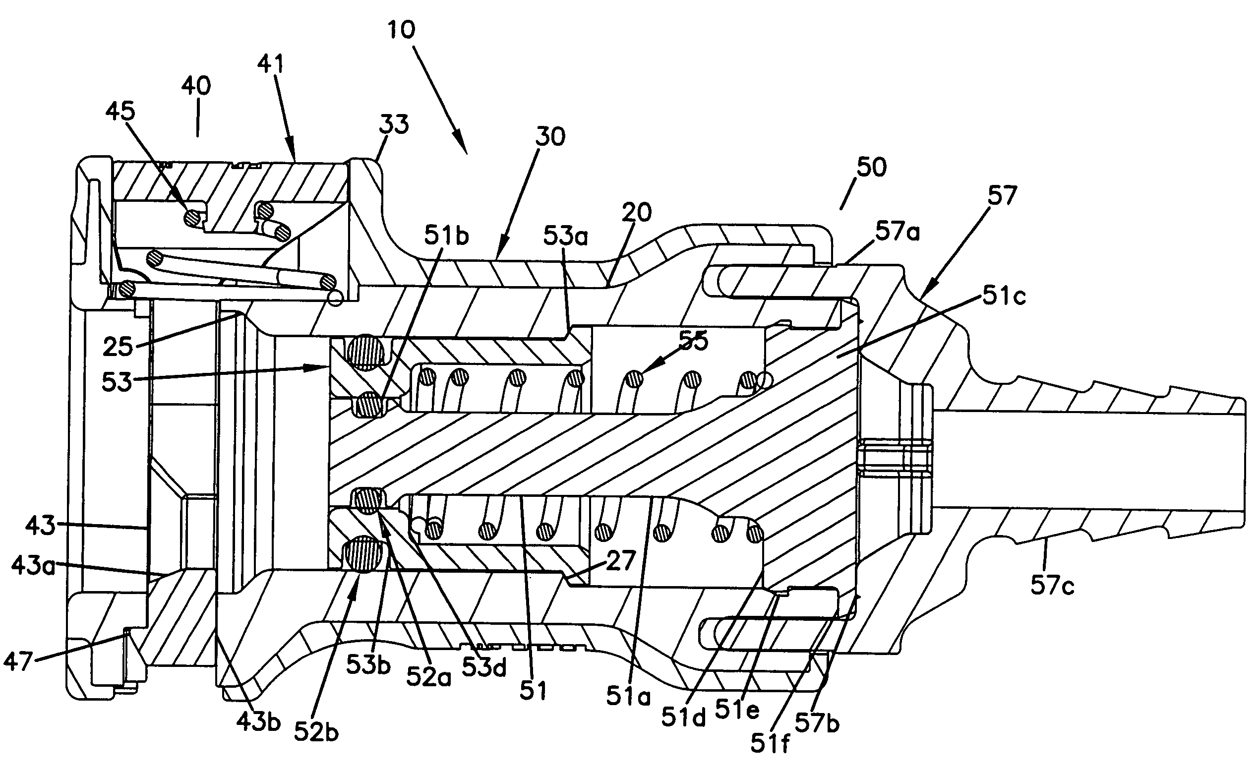
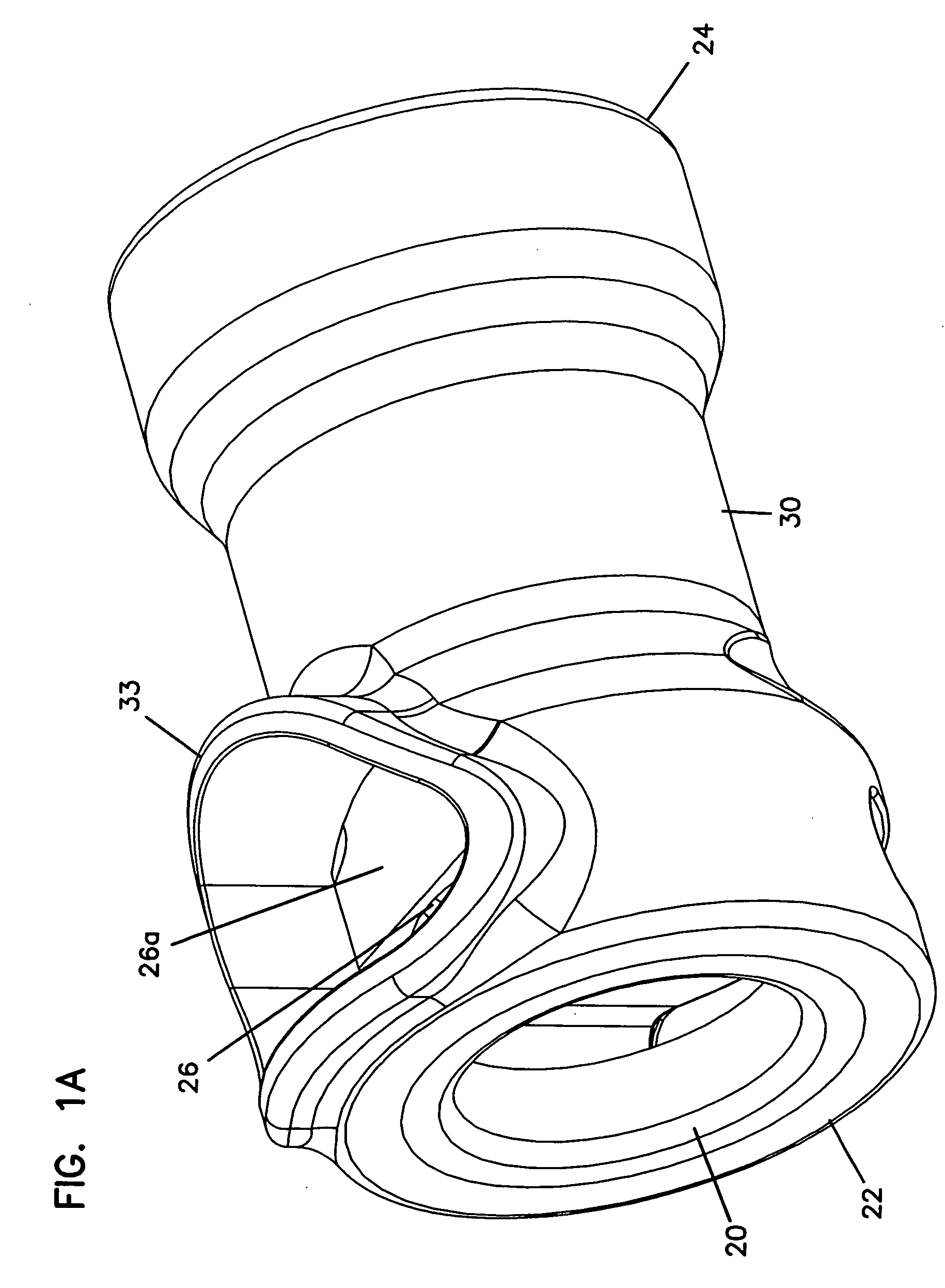
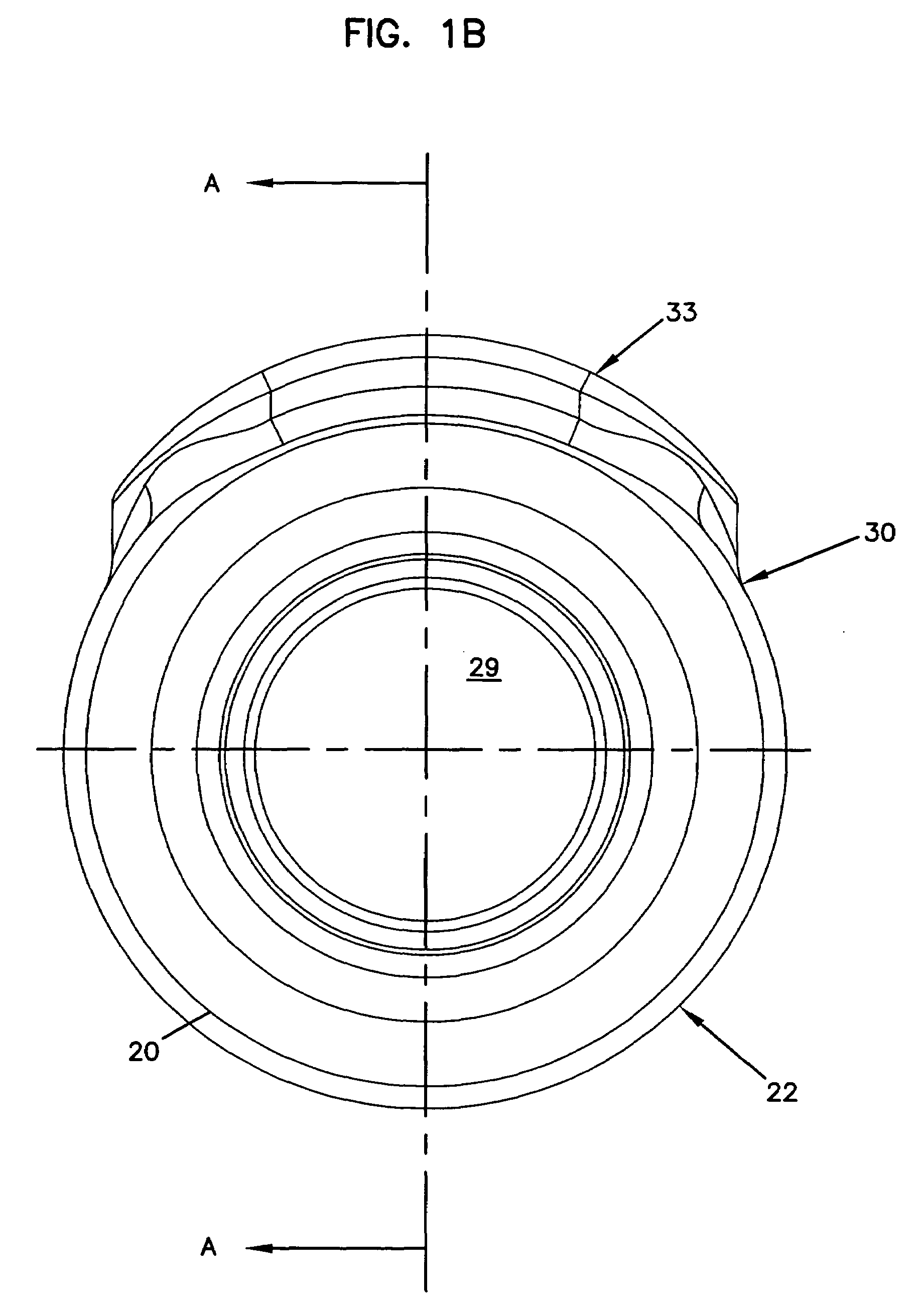
[0040]FIGS. 1A through 1E illustrate one preferred embodiment of a coupler body 20 with a soft overmold 30. The coupler body 20 includes an outer surface being an outer sidewall 21 with a first end 22 and a second end 24. Preferably, the outer sidewall 21 is a radially shaped outer sidewall forming a substantially cylindrical shaped coupler body. An opening 29 extends through the first and second ends 22, 24, and substantially resembles a longitudinal bore extending through the coupler body 20. The body defines a slot 26 proximate the first end 22. Preferably, the slot 26 extends i...


PUM

PropertyMeasurementUnit
couplingaaaaaaaaaa
dimensionsaaaaaaaaaa
plasticaaaaaaaaaa

Abstract

A coupler device for fluid transport that includes a body with an outer sidewall. The body defines a slot disposed proximate one end, and extends in a direction transverse to and through the outer sidewall. A latch assembly is connected with the body. The latch assembly includes at least one outer member being disposed on the outer surface of the body, and is externally exposed of the body. The inner member is connected with an inner member being disposed through the slot. A soft overmold portion is formed over the outer sidewall of the body. The overmold portion includes a shroud portion that extends outward from the outer sidewall, and partially covers the outer member of the latch assembly.

Description

RELATED APPLICATION[0001]This application is a divisional of U.S. patent application Ser. No. 10 / 612,475 filed on Jul. 2, 2003 which is still pending, the entirety of which is hereby incorporated by reference.FIELD OF INVENTION[0002]This invention is related to a fluid connector and method of making a molded connector. More particularly, the present invention is related to a fluid connector with a soft overmold.BACKGROUND OF THE INVENTION[0003]Fluid couplers used in fluid transport applications are common and widely used. Typically, such connectors require proper dimensioning so that seal and / or assembled surfaces can be maintained to provide a no leak, no spill connector. These connectors also employ quick connect / disconnect features having manually operated latches for connecting other pieces of fluid dispensing equipment. Further, valve control parts and assemblies may be employed for controlling fluid flow. Such latch parts and assemblies are often disposed external the main flo...

Claims


Application Information

Patent Timeline
Patent Type & Authority Patents(United States)
IPC IPC(8): B23P25/00B29C45/00F16L37/00F16L37/084F16L37/34
CPCF16L37/0841F16L37/34Y10T29/49414Y10T29/4998Y10T29/49405Y10T29/49412Y10T29/49417
Inventor DECLER, CHARLES PETERWILHELM, GRANT ARMIN
Owner COLDER PRODS
Why Eureka
Try Eureka