Pre-assembled sealing connection

a sealing connection and pre-assembled technology, applied in the direction of couplings, pipe connection arrangements, joints/fittings, etc., can solve the problems of high cost of coupling, inconvenient installation of the tube on the ribbed rear cylindrical region referred to as a serrated spigot, and inability to reliably mount the tube on the ribbed side cylindrical region referred to as a spigot serrated, etc., to reduce the risk of leakage, improve the effect of coup

Inactive Publication Date: 2004-11-25
HUTCHINSON SA
View PDF12 Cites 85 Cited by
  • Summary
  • Abstract
  • Description
  • Claims
  • Application Information

AI Technical Summary

Benefits of technology

The invention aims to make the coupling more effective while ensuring that it is completely tight, reducing the risk of leakage. This is achieved by using a single element that guarantees leaktightness.

Problems solved by technology

The technical problem of this patent text is not specified and requires further analysis and interpretation.

Method used


Image

  • Pre-assembled sealing connection
  • Pre-assembled sealing connection
  • Pre-assembled sealing connection

Examples


Embodiment Construction

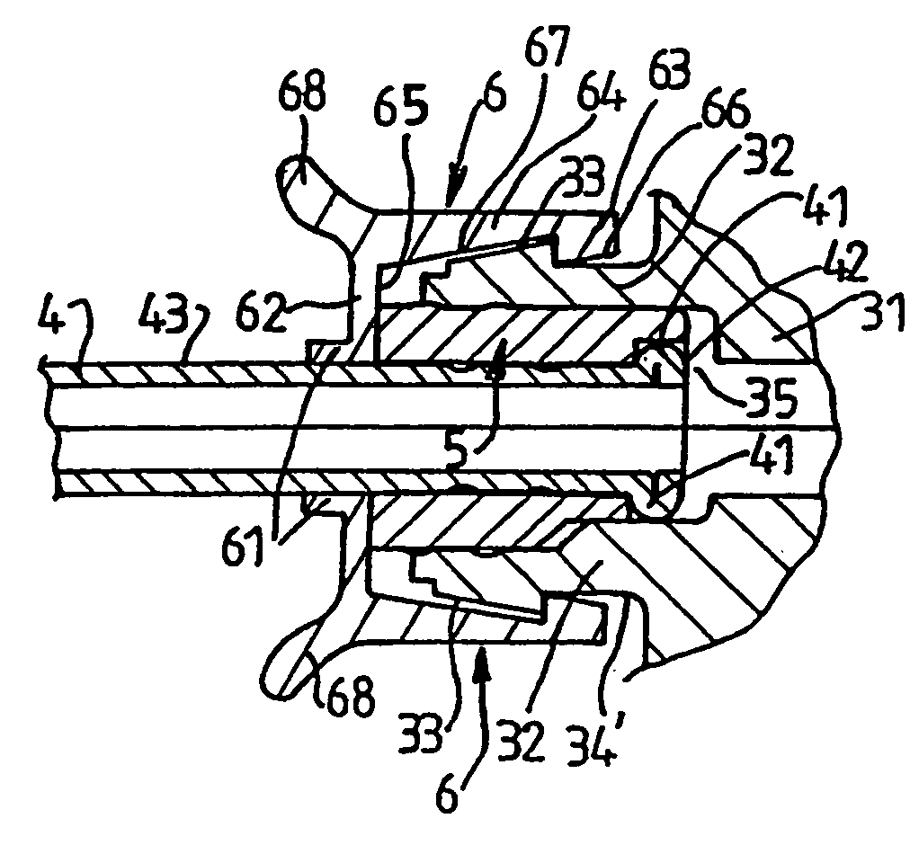
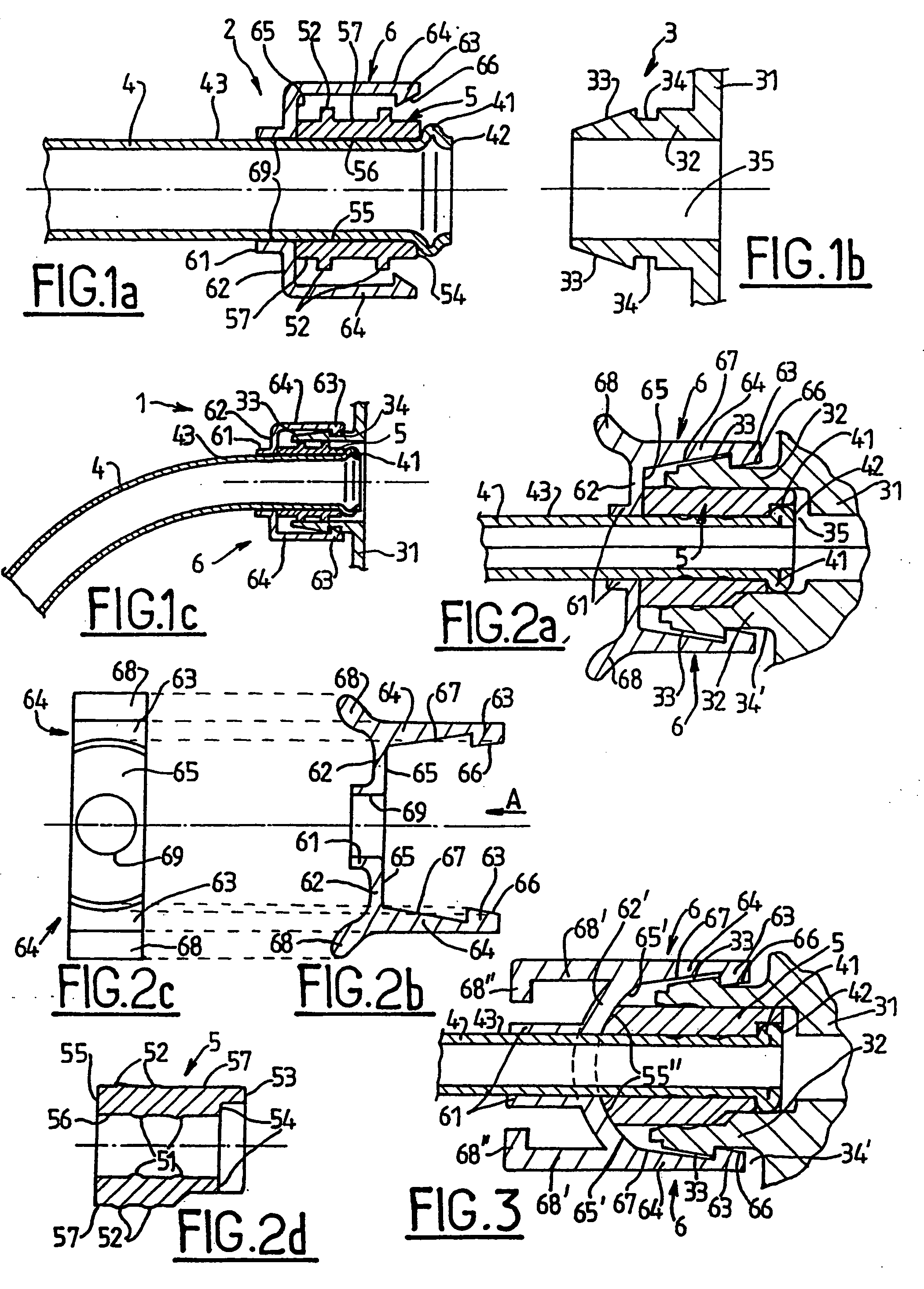
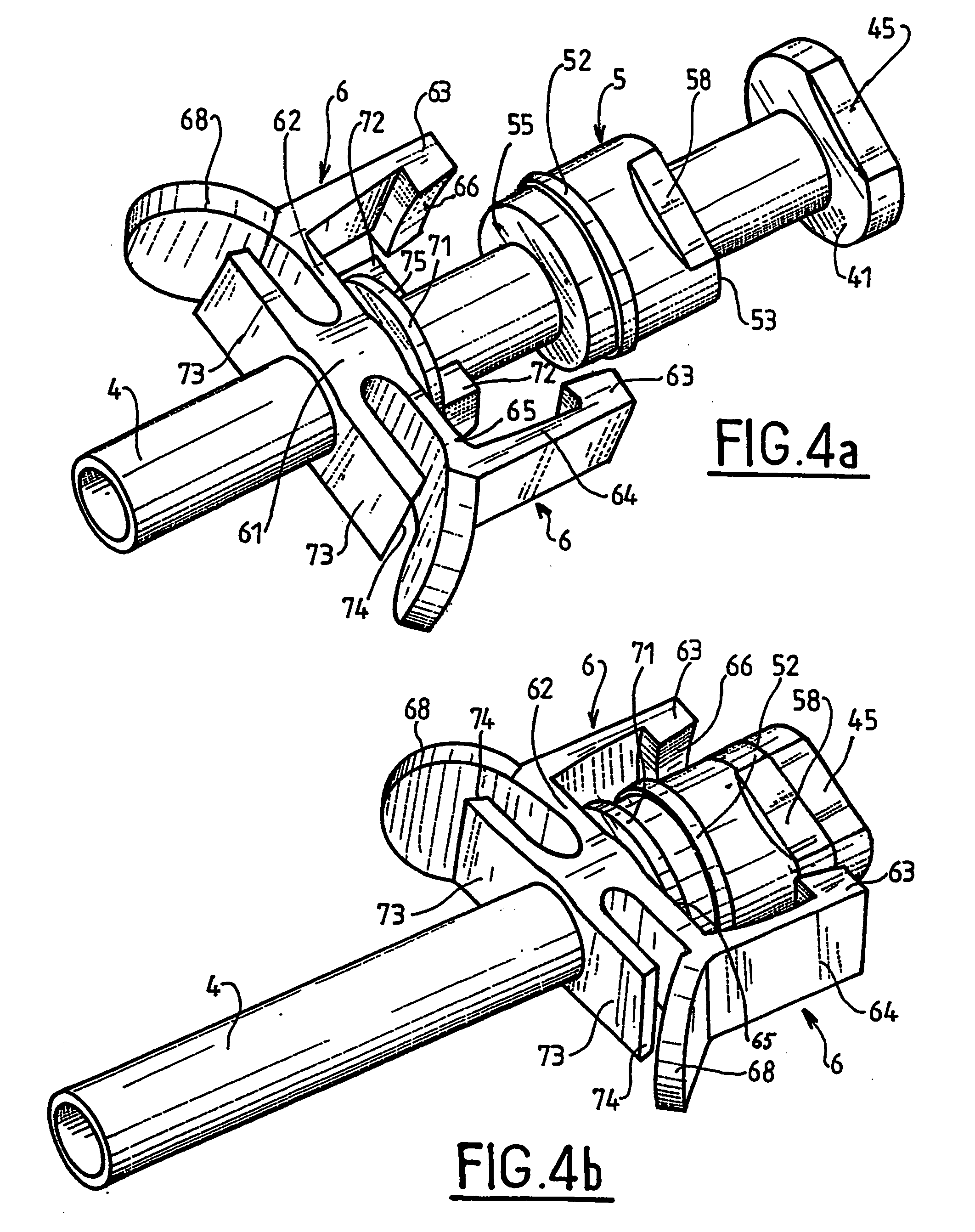
[0023] The invention provides a quick coupling pre-assembled on a rigid or semi-rigid tube 4 (i.e. sufficiently rigid to provide sealing), e.g. made of metal or of plastics material, which tube is shaped at its front end 42 so as to form an annular bead 41. This shaping may be performed cold or hot. An elastomer sealing element 5, e.g. made of rubber, and threaded on the tube 4 (or overmolded thereon) serves to provide sealing against the tube 4 and against the endpiece 3 by compression delivered by a fastener device 6, e.g. made of metal or of thermoplastic material, which is threaded on the tube 4 and which becomes fastened to the endpiece 3 which may be of conventional type, e.g. an endpiece of the kind commonly used by automotive manufacturers in cooling circuits. The fastener device 6 may be threaded onto the tube 4, in particular by force, or it may be overmolded thereon.

[0024] The coupling presents various components each corresponding to a function, namely:

[0025] a tube 4 fo...


PUM

PropertyMeasurementUnit
Forceaaaaaaaaaa

Abstract

The invention provides a pre-assembled coupling for leaktight coupling of a fluid transport tube and an endpiece provided with at least one coupling element. The coupling comprises: a said tube, which tube presents an annular bead at a front end; a fastener device slid onto said tube and presenting at least one fastener element complementary to a fastener element of the endpiece; and an elastomer sealing element disposed around said tube and presenting an inner surface for providing sealing with an outer surface of the tube, and an outer surface for providing sealing with the endpiece. The invention is particularly suitable for fluid circuits in motor vehicles.

Description


Claims


Application Information

Patent Timeline
Owner HUTCHINSON SA
Why Eureka
Try Eureka